Hinge tests

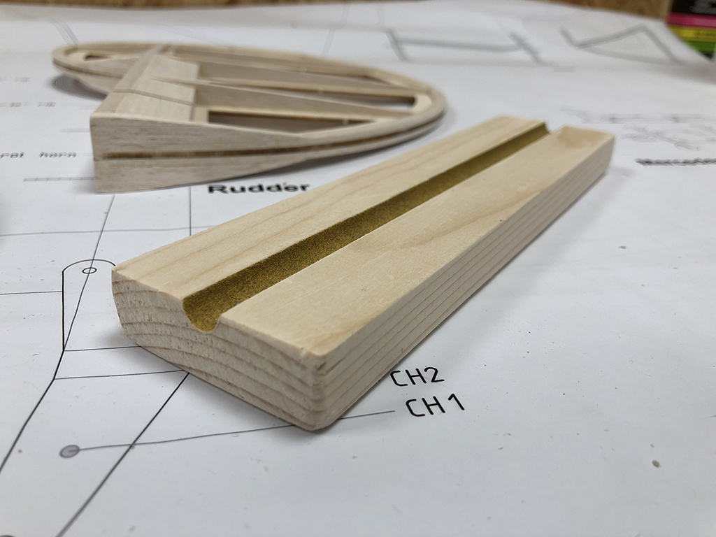
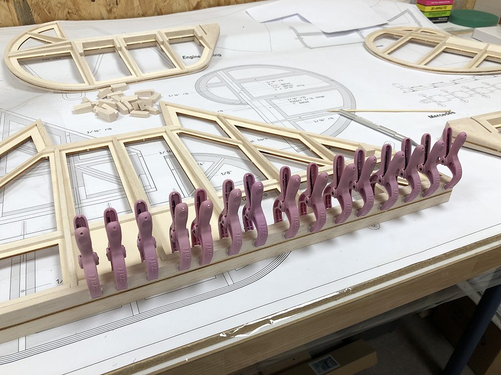
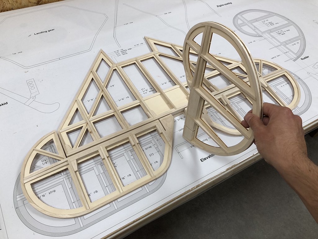
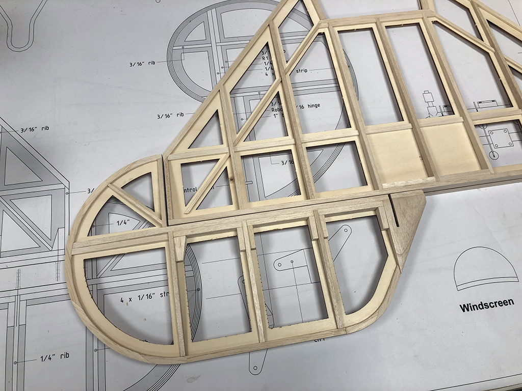
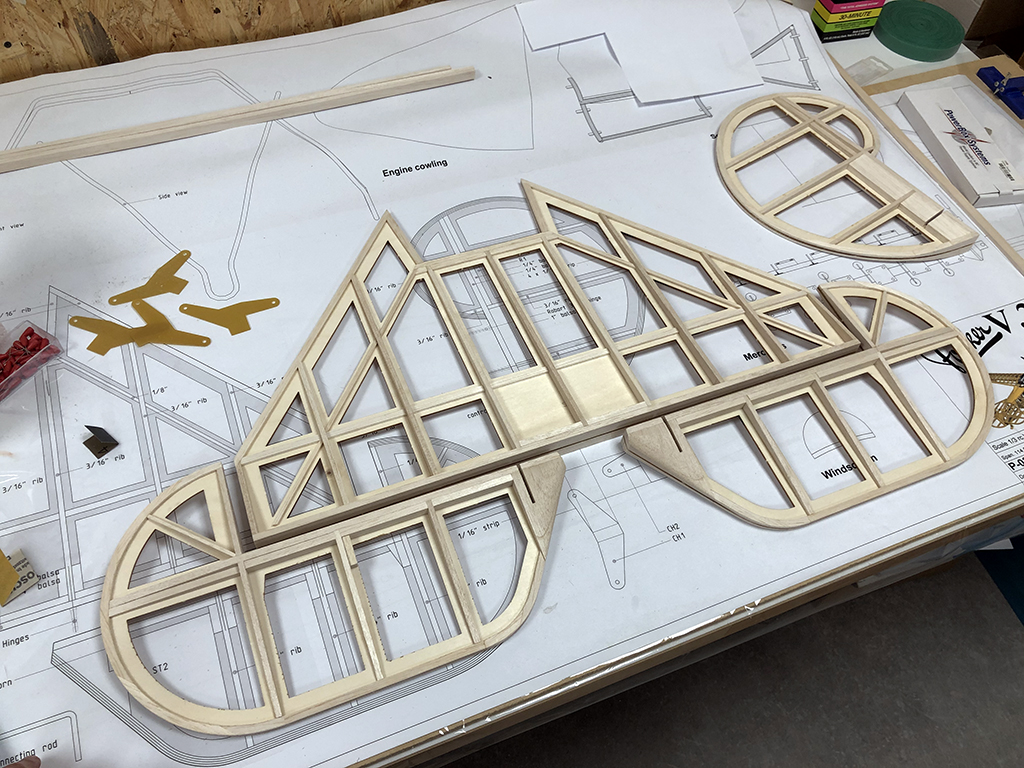
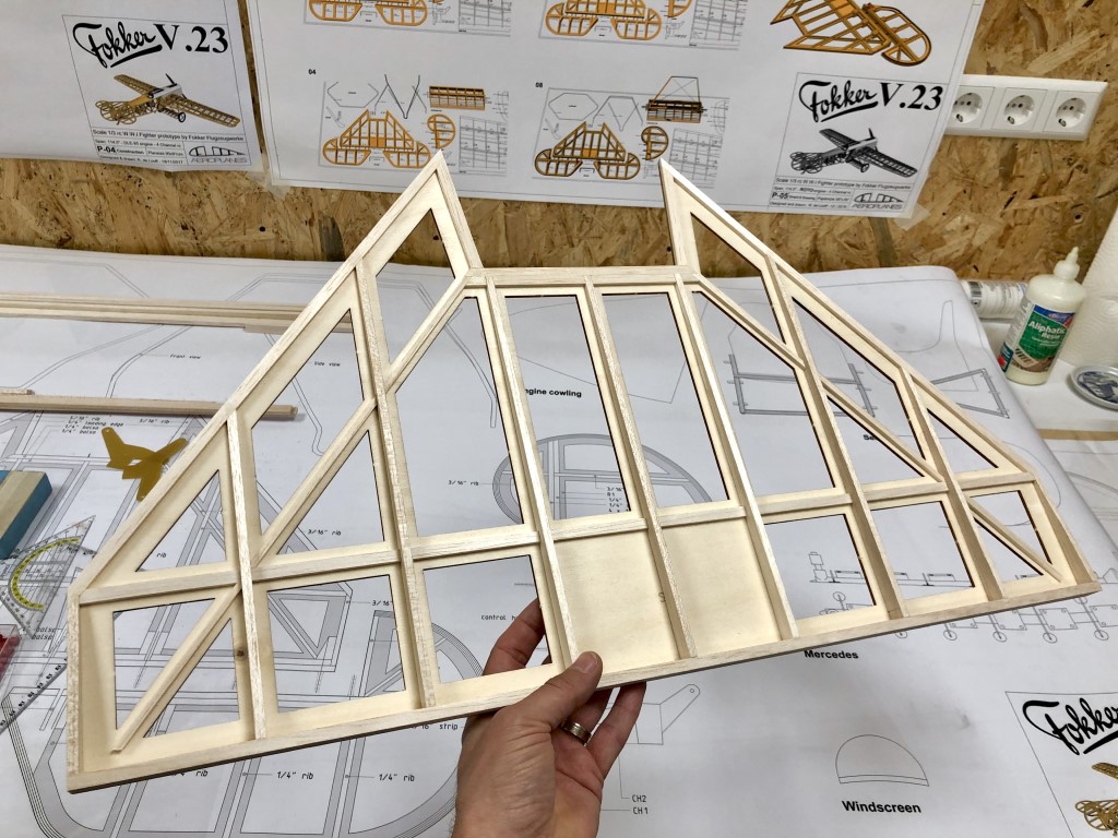
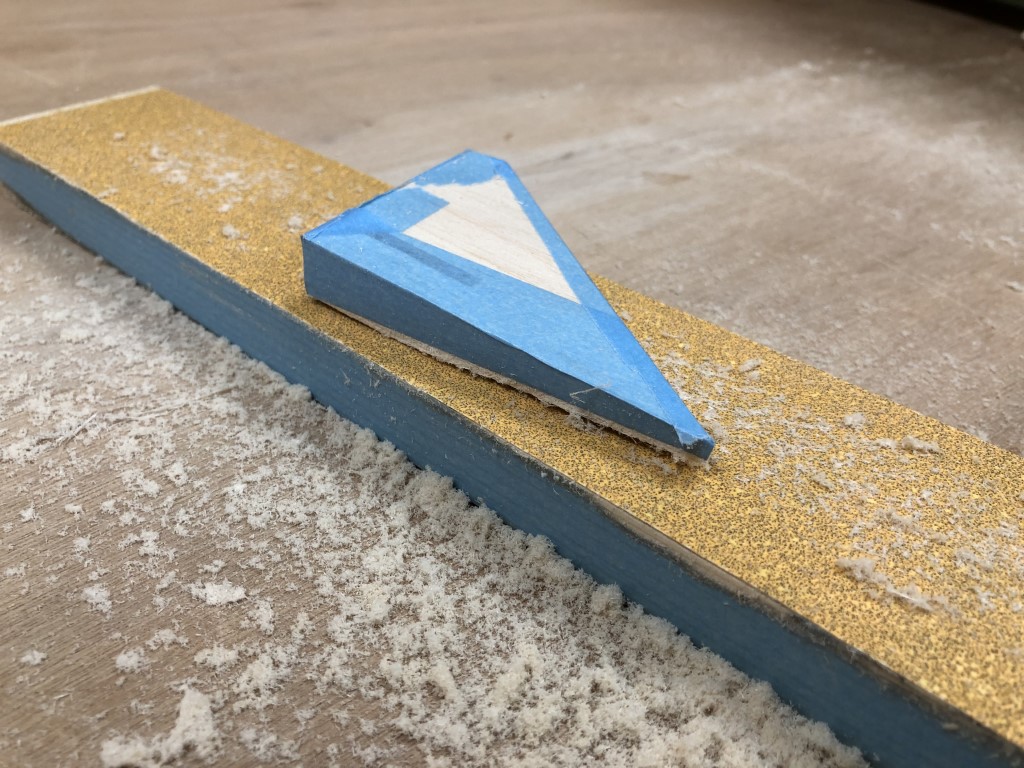
I’ve finished up the rudder by rounding off the edges and blending in the transitions to the main spar:

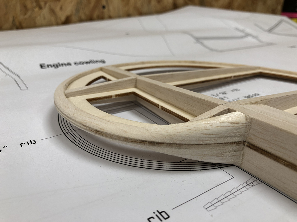
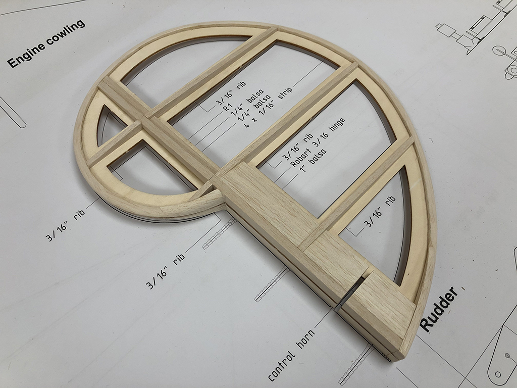
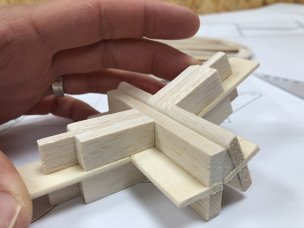
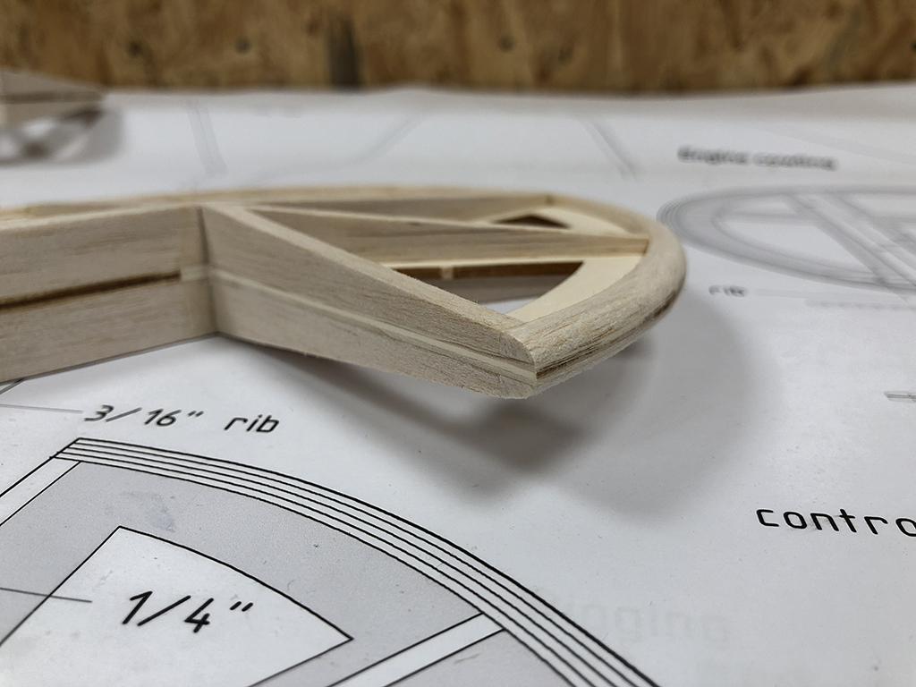
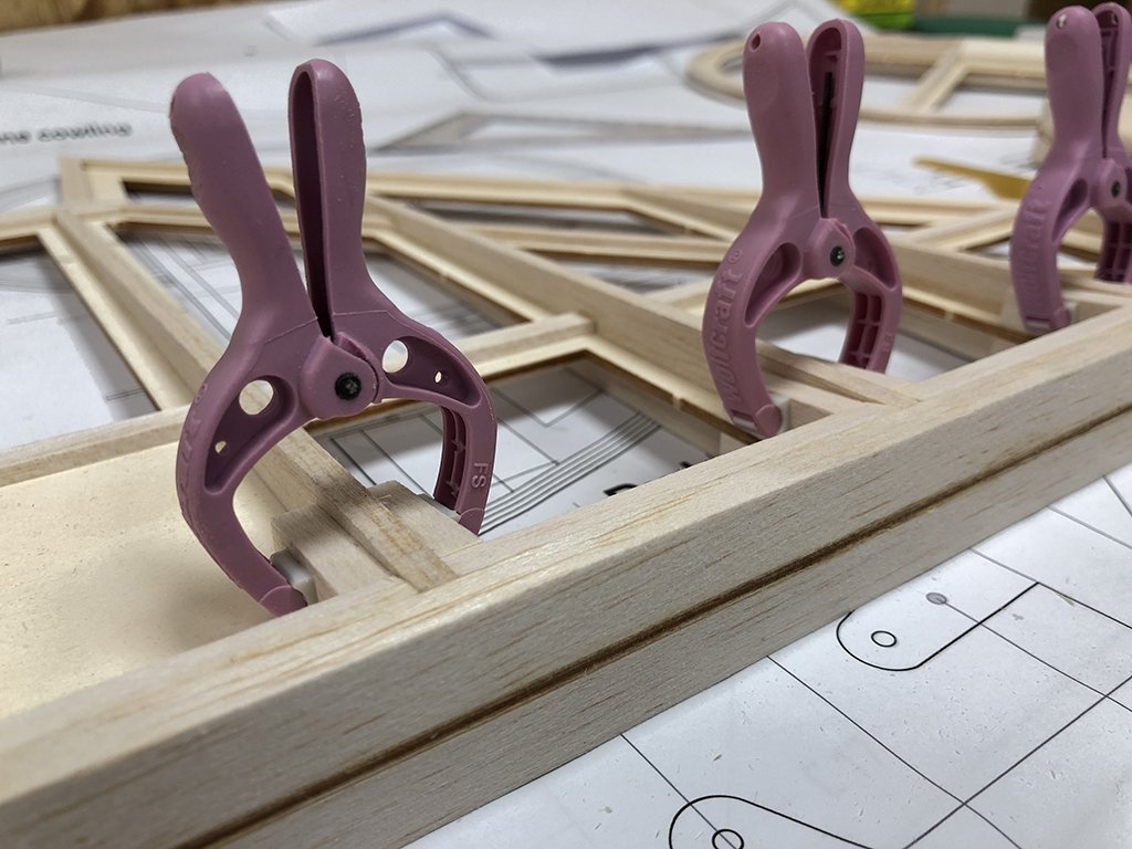
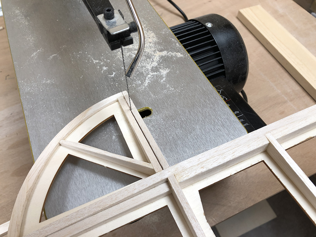
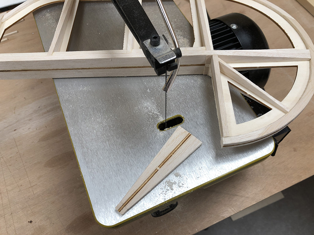
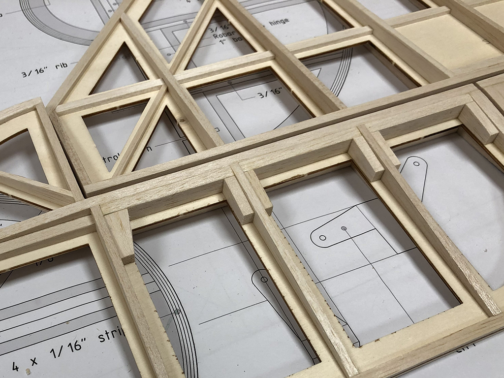
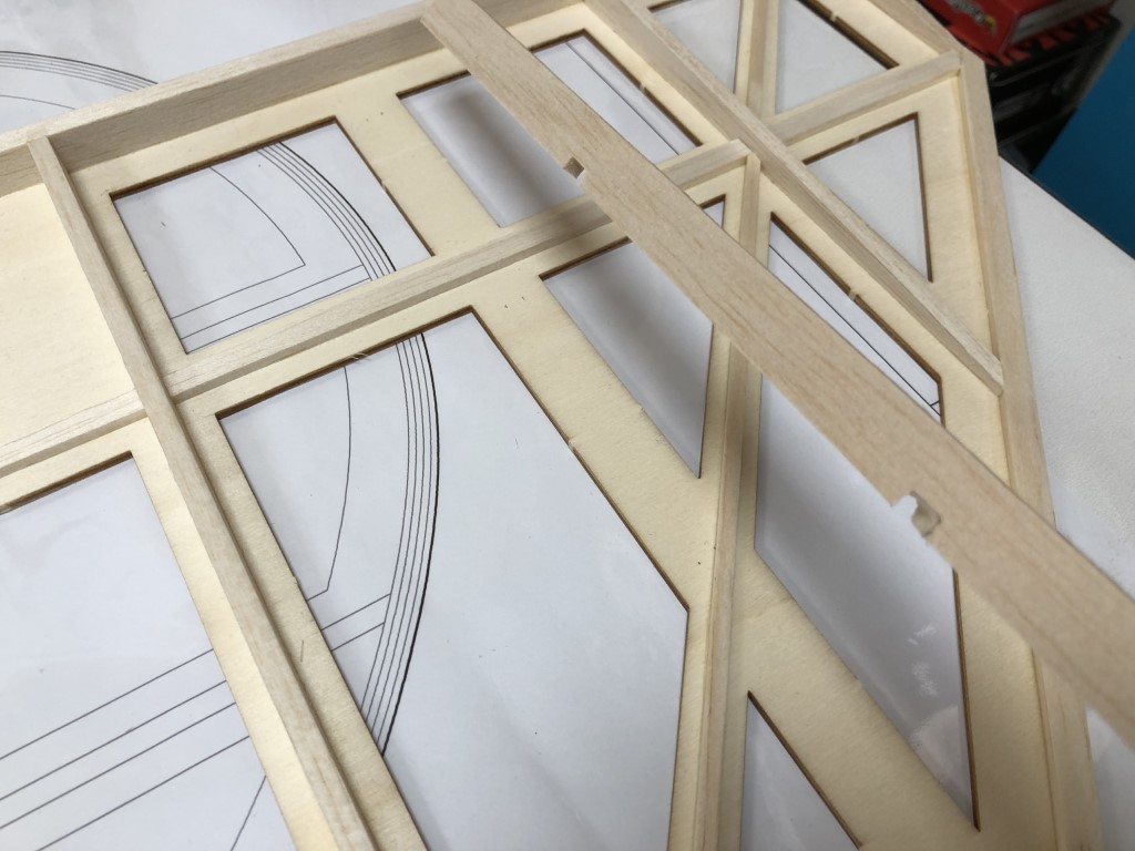
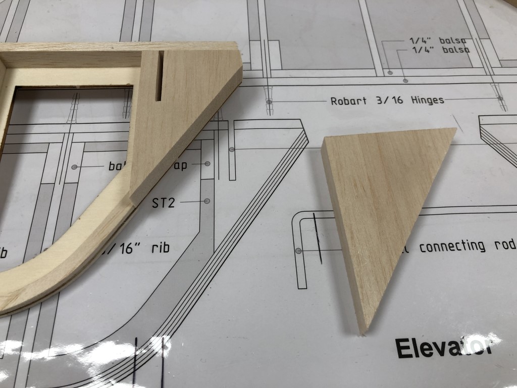
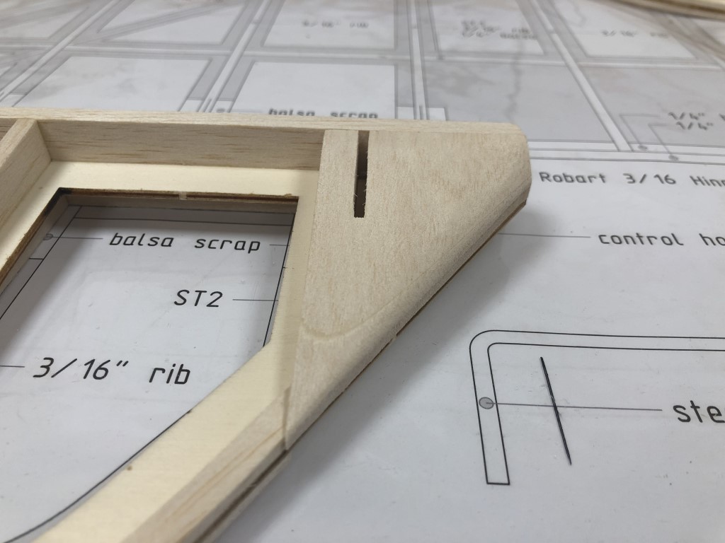
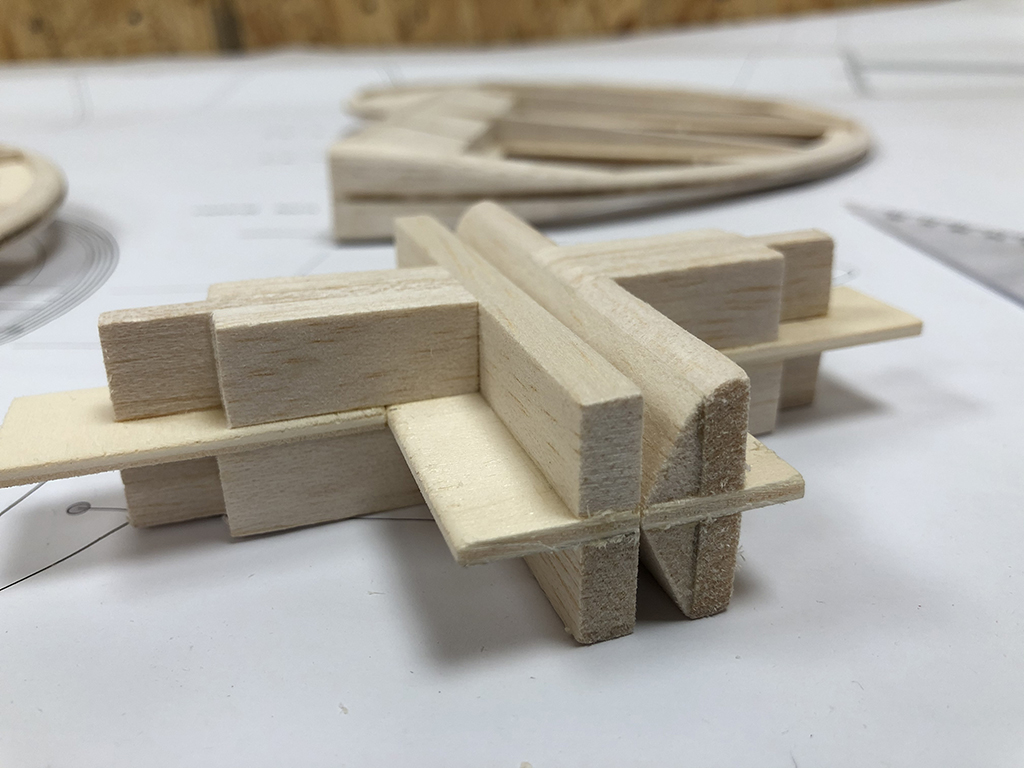
Now I’m moving onto the hinges. I have made a test piece to find the best hinge point, maximum throw and LE shape of the control surfaces. Looks like the best solution is the classical model hinge with the hinge point of the Robart hinges right between the surfaces. The hinge gap comes out great, very tight fit:

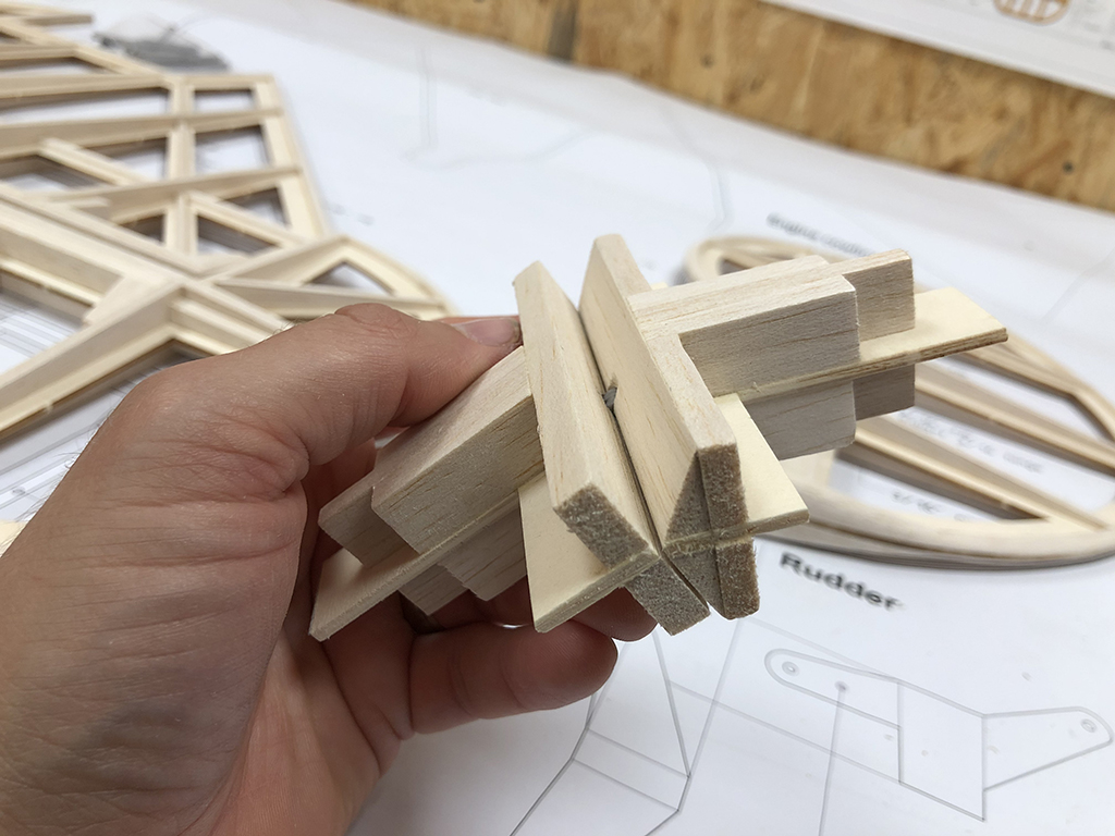
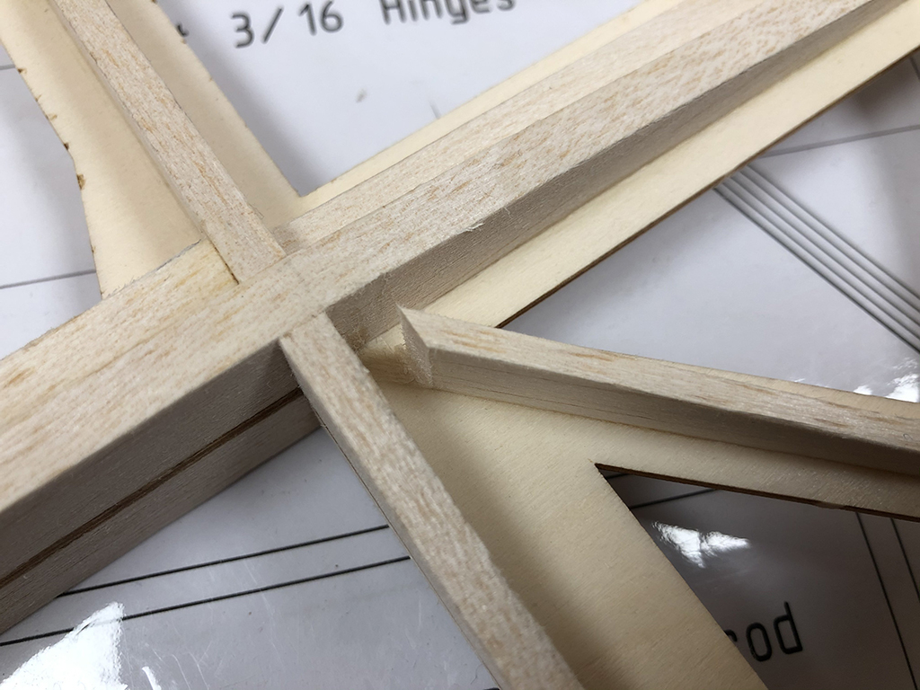
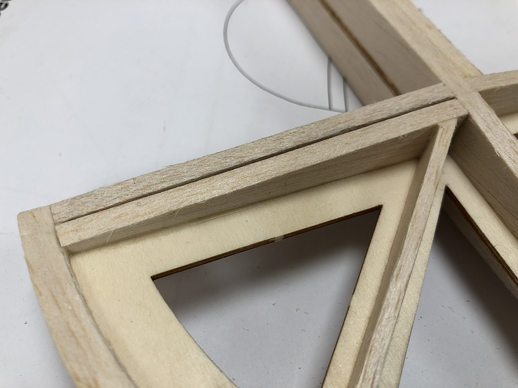
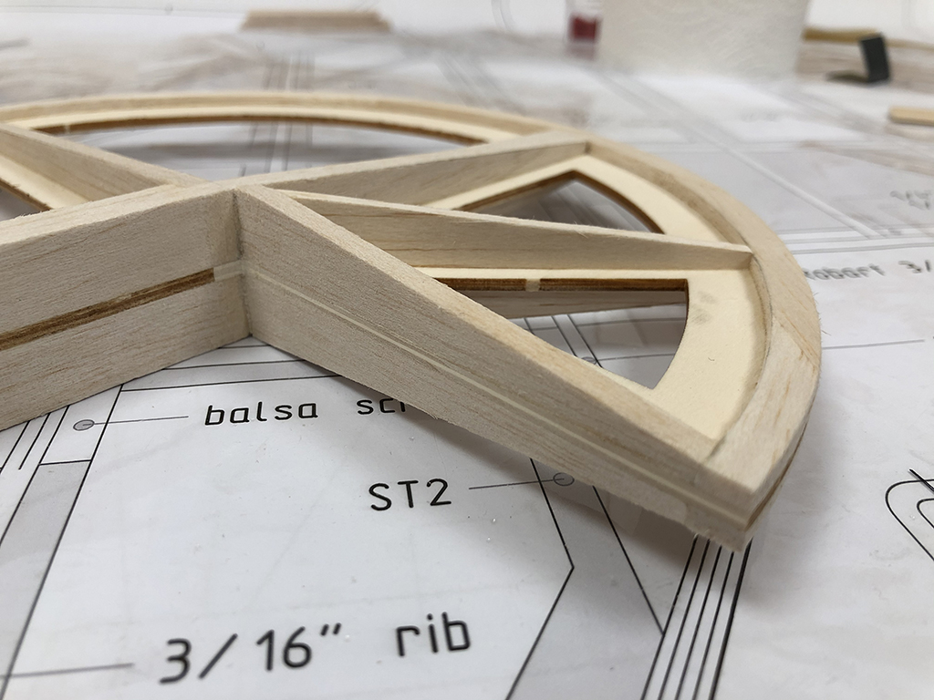
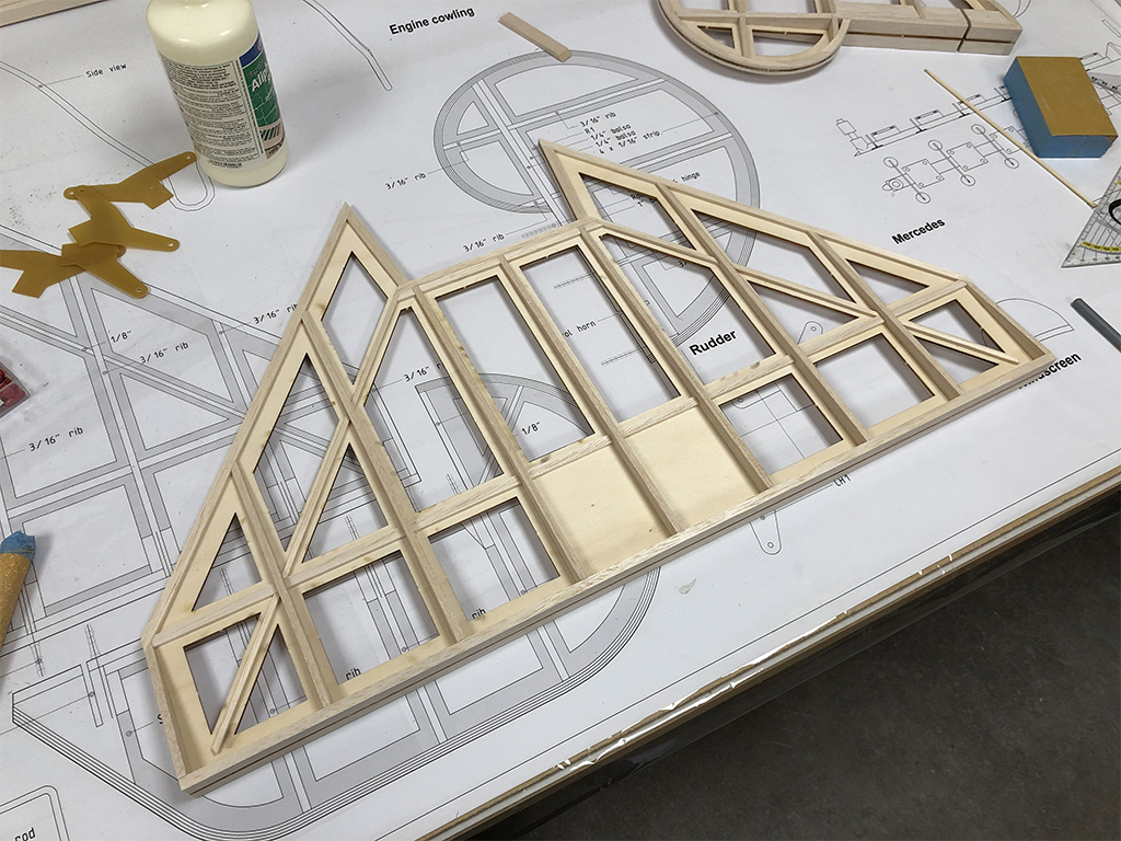
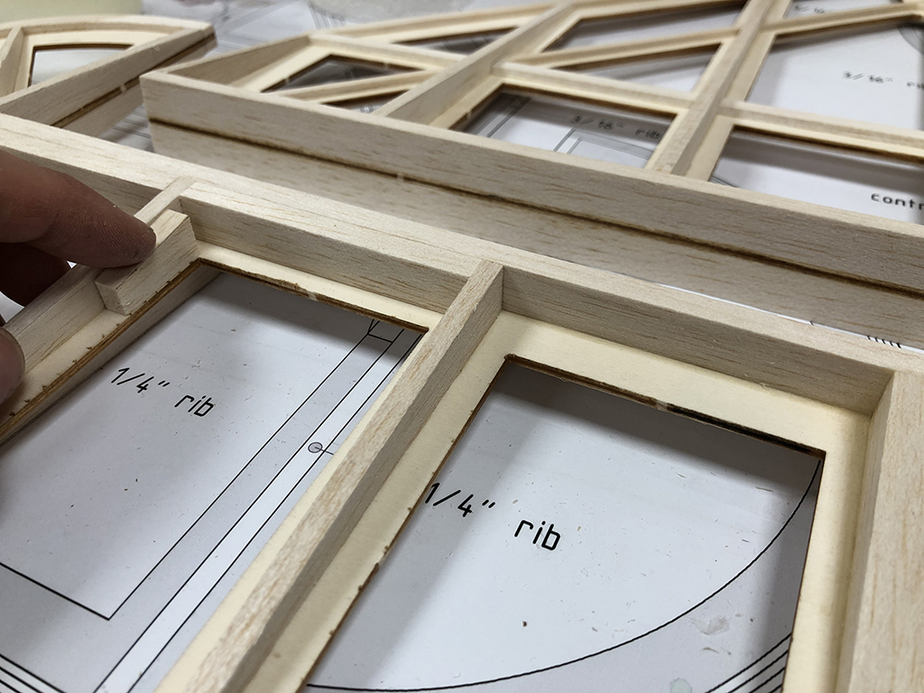
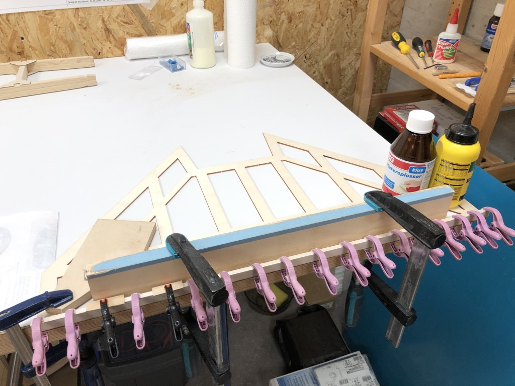
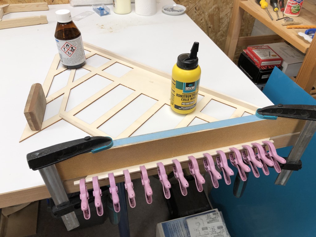
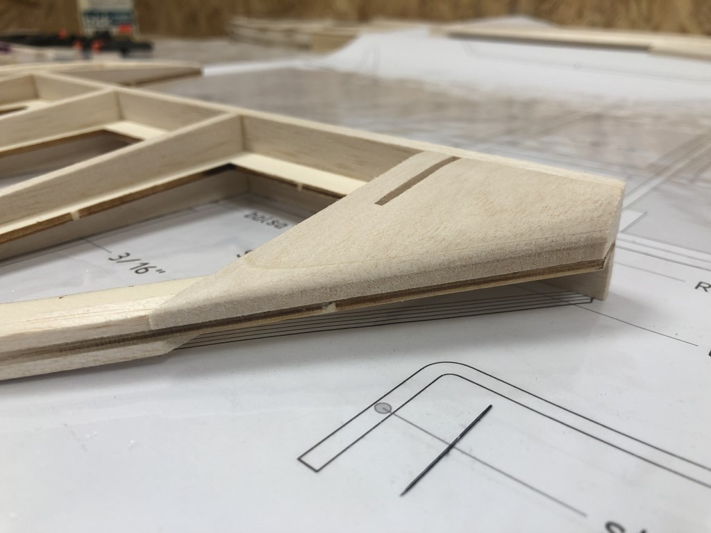
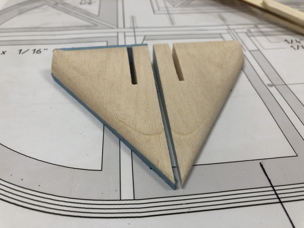
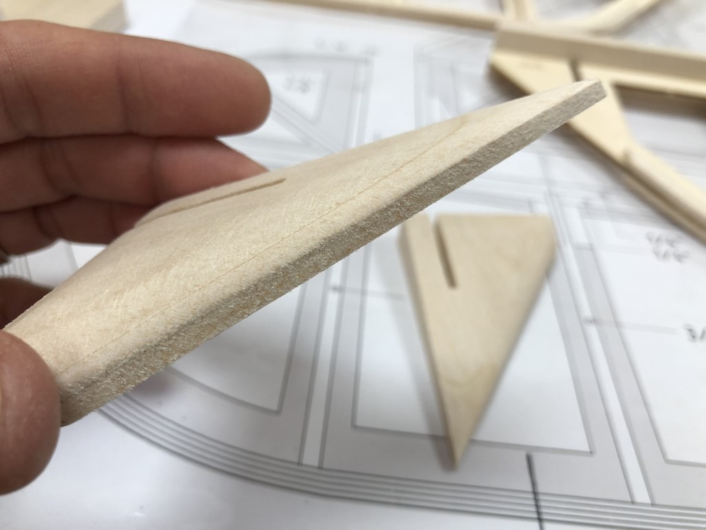
Though the transition from the angle LE to the ribs is a bit sharp, both visually and aerodynamically. So I tested rounding that edge off as well. Looks way better, and makes for a smooth transition to the upper and lower surfaces:

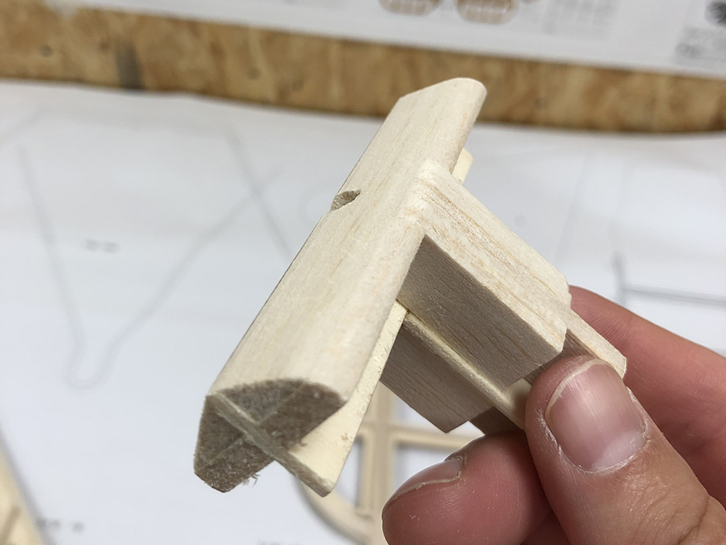
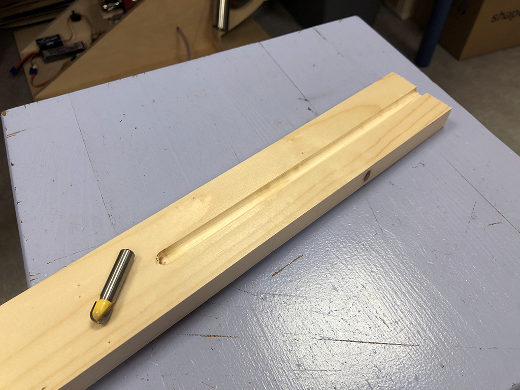
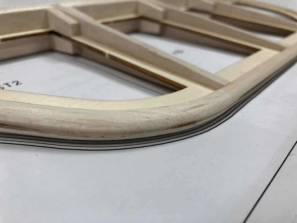
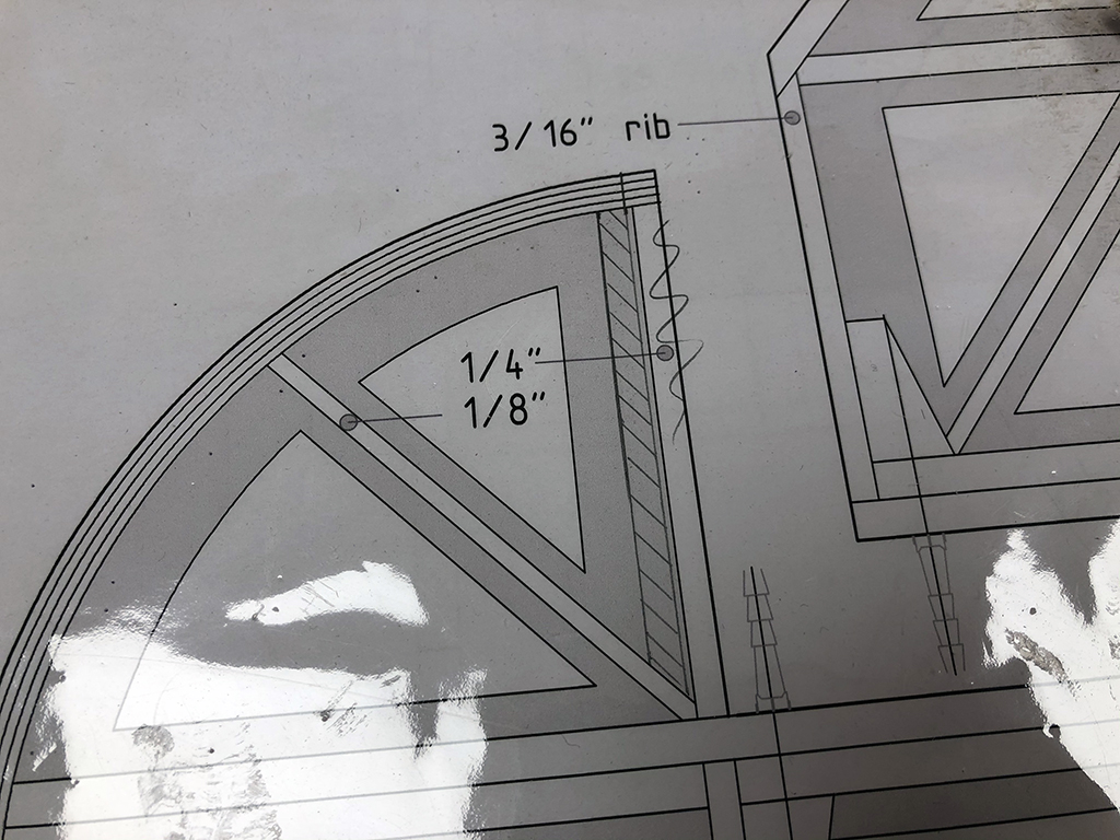
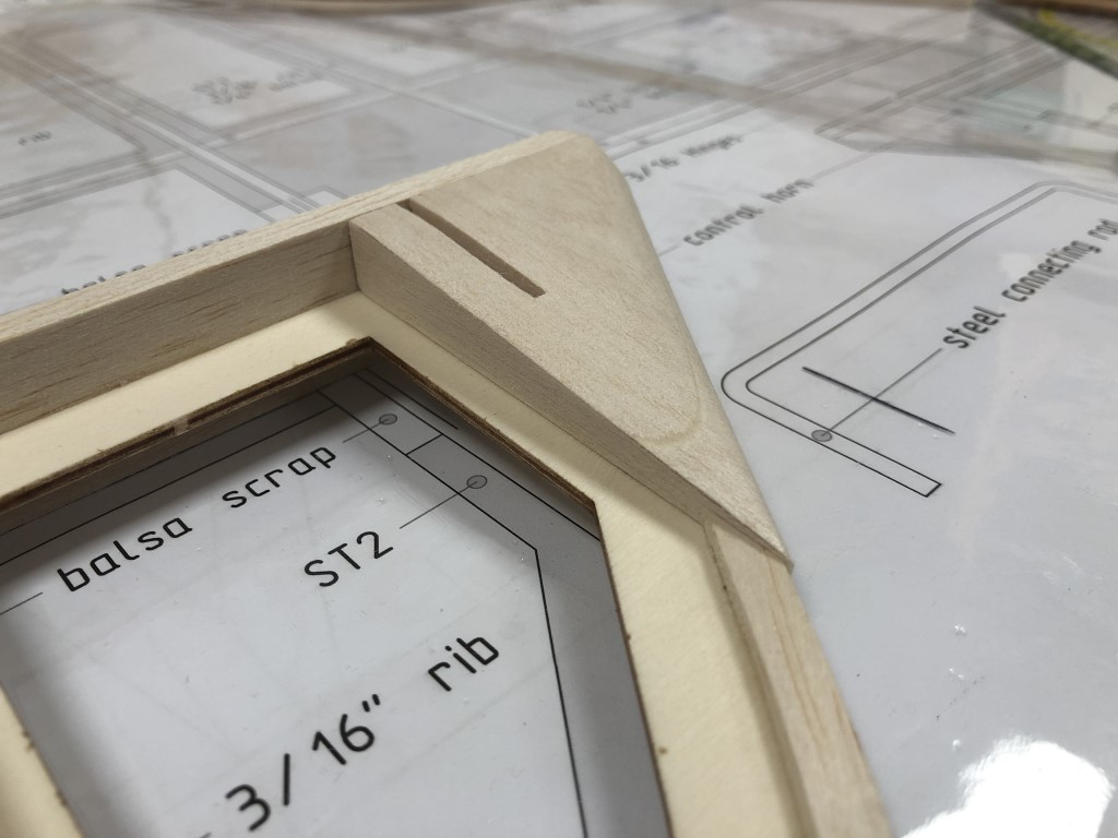
The resulting gap is also very small and at this scale it won’t be noticeable at all. Originally, the control surfaces had a tubular frame with the LE being a tube hinge in a concave wooden beam, but my tail section is too thick and the wood doesn’t have enough depth to create a perfectly round LE (or at this thickness, that wouldn’t look right for a plane from 1918) so I like the way this turned out:

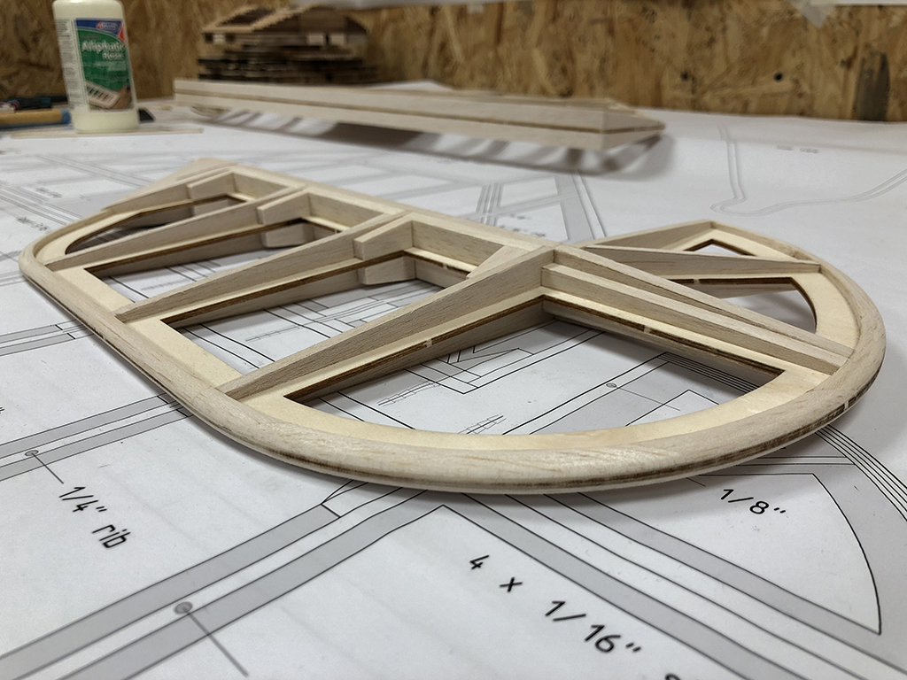
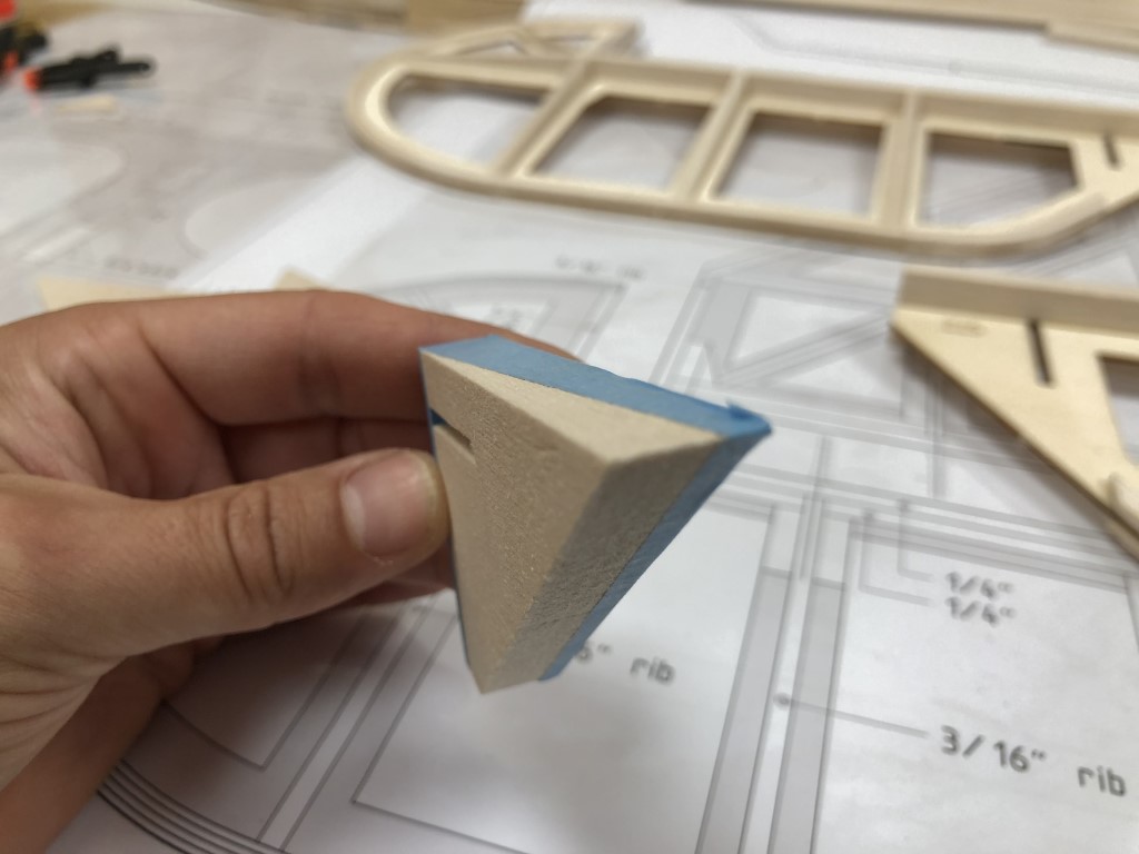
Also, the maximum throw seems to be more than enough at 22 degrees. The round edge makes for a smoother transition from stabilizer to elevator too:

Radius sanding block

To get a consistent radius around the tail feathers I came up with the idea to make a radiused sanding block myself. So I bought a router bit in the exact radius of the control surface edges (the ply, two layers of balsa and some extra space for the sanding paper), and routed a slot in a piece of soft wood:

Then, with the help of a long wooden dowel and Pritt stick I glued a strip of sandpaper in the slot:

And from there on, it really is a very simple process. The sanding block automatically centers over the edge because of the matching thickness. Pretty happy with the result!

Difficult to catch in a photo, looks even better in real life, but the radius is nice and consistent around the elevator and the thickness of the edge is perfect for imitating the original tube structure:

Tail feathers structure finished

No new developments today, only more production work.. I’ve made the last set of 28 hinge blocks:

Cut the spar doublers for the stabilizer and glued them in-between the ribs:

And lastly glued the hinge blocks in place:

This finishes up the complete structure of the tail feathers!

Next step is to sand the contours to a round edge to mimic the original tube construction, and to install the hinges and sand the leading edges of the control services to allow them to hinge in the first place.

Fixing the elevator

I had to change the design of the elevator because the part before the hinge line was to wide, preventing the ribs from aligning as intended. This is a small error in the plans which I only spotted after I built up the tail feathers. So, I need to move the forward rib of the elevators inward, plus some extra space to allow the elevator to move around the stabilizer freely:

I fixed this by first cutting the diagonal rib and cleaning up the joint with the main spar:

Then I glued in the new rib. I didn’t want to cut the incorrect rib off first, because this would weaken the structure, allowing the ply to deform again (this rib played a crucial role in aligning the ply core in the first place).

The next step is to cut the old rib off, I stayed clear from the new rib to prevent scratching it, and used by scroll saw to ensure a straight cut:

And there it is, a slice of rib:

After gluing in the lower rib and some sanding, it looks perfect again, you almost can’t tell anything changed:

Now, the ribs do align as intended, mission accomplished!

Also, I glued in the support blocks to the back of the spar and around the hinges. I slightly slanted those blocks so they wouldn’t protrude through the covering later on:

Now, I need to repeat this exercise for the right elevator and then it’s time to move onto finishing the stabilizer!

More work on the tail feathers

After an unforeseen break I started building again. Past few weeks I cut the ribs for the underside of the stabilizer en glued them in place. A lot of sanding, cutting and trial fitting as all of the wood apart from the ply core is hand cut and scratch built. Very happy with the result though:

Next step is cutting the inserts that go in-between the ribs. An easy but time-consuming job, as we need 28 pieces of spar, and 52 slanted blocks that go in the direction of the ribs. I like to build as straight as possible without using too much glue, so I’ll take my time for this step in the build:

The leading edge of the control surfaces will be sanded round later on, and the Robart hinges will sink into them so the hinge point lies between the two leading edges of the elevator.

By the way, I discovered a small error in the drawings, as the front part of the outer rib on the elevators shouldn’t be in line with the aft part of the rib. That way, the ribs of the stabilizer and elevator do not align. So I need to cut away some pieces of the elevators and glue in new ribs offset to the outside of the elevator. No big deal and certainly part of building a prototype. I plan to finish up all the work on the tail feathers before going back to the fuselage again (rounding all of the edges, preparing for the control horns and hinges etc.).

Upper stabilizer ribs done

Made some progress on the stabilizer. First I built the outer edges (1/8″ on the front, 1/2″ on the back) and then the crossbar. After that, I’ve cut all ribs to the right length and made the notches for the crossbar:

When the rib fitted nicely, I cut the slope in and glued it on with the stabilizer clamped to the table to ensure keeping the whole assembly as straight and true as possible:

All ribs are cut from balsa sheets. First using the balsa cutter to get the correct height, which is quick and easy. Then, mostly the skewed notches take some time, but it’s fun to do and so much nicer and stronger than straight notches of pre-cut ribs. I enjoy these scratch building parts of the build. When the notches are finished, I cut the slope in the rib using my scroll saw machine:

Finished all the ribs on the upper side of the stabilizer! I’m very happy with how straight and true it came out:

A few close ups of some nice details:

And for scale reference… could’ve been a flying wing too if you look at it like this:

Firing up the engine!

What a lovely evening! Tonight I started my ROTO for the first time (or any gas powered engine for that matter). First I checked all the settings on my transmitter, throttle travel, choke, spark switch.. fueled the test stand, flipped the prop once with choke, turned the choke off, flipped it once more.. and there it was, the lovely purring sound of a happy four-stroke two-in-line engine! It ran so smoothly… and it didn’t stop until I flicked the ignition switch on my remote. Loved it!

After running idle for a little while, it already started picking up very nicely when revving up. The video below isn’t completely idle, just a few clicks of throttle, but it does run like a charm. It was a bit louder than I expected it to be, but running it underneath the overhang of my garage roof didn’t help at all, and even more so because I was running it in the corner of my house and garage, I don’t think measuring the sound level was representative, so I’m still hoping it’ll be okay in the end, also because the exhaust has to build up a layer of carbon inside for the optimal muffling effect.

Starting stab & finishing engine

It’s been a little while since my last post but I haven’t been idle. I started building up the stabilizer. To ensure it is nice and flat, I clamped it onto the workbench while gluing the leading and trailing edges:

Working my way around the stabilizer:

After this, I can glue on the main ribs and by then it will not deform anymore and I can continue building up the rest of the structure without the guidance of the building table.

But first, let’s get back to the engine. I look forward to hearing it run, want to finish the firewall so I can continue building up the fuselage, and I’m curious to learn how my custom muffler holds up!

I finished the installation of the muffler by joining the front exhaust elbow to the muffler using the silicone tube provided by ROTO. I did however replace the tie wraps with spring clips, as they are way more sturdy, air tight, and easier to take on and off. I also think they look better than tie wraps too:

Finally, the propeller is on! I drilled the holes and attached it, what a pretty sight this is! Can’t wait to see this running…:

But before I can enjoy the sweet sound of a multi cylinder four stroke, I need to build up my test stand for this last and final phase of preparing the engine to go into the model. I’ve placed the throttle servo and fuel tank at the exact same height as they will be in the fuselage, though in there it will be a lot tighter:

Also, one of the things to tackle was building up a fueling station, as I am new to flying on gasoline, I didn’t have any field equipment either..

So now, I’m ready for breaking in the engine :-). To be continued!

Working on the elevators

The elevators are built with a solid piece of balsa on the inside to support the control horns. On the plans, the 3 mm outer edge continues all the way to the inner end of the elevator, but I decided to build this whole area out of one solid piece of balsa – this is easier to build and also makes it easier to get a smooth transition from the block to the edge.

I first laminated a piece of balsa out of two 1/4″ thick layers, sanded the perpendicular edges straight, and then I placed it on the elevator to trace the outlines and cut the piece to the right size, including the opening for the control horns:

Then, I sanded the piece to shape. It’s slightly oversized (by 0.5 mm) because I didn’t yet glue it on. I have to build four blocks and this way it’s easier to compare the result and modify them until I have four identical pieces. After gluing them on I will do the final sanding:

It’s a complex shape though, because the thickness should be 3 mm all along the outer edge:

While the inner side runs in a slope from 1/2″ to 1/8″:

I have developed a neat little trick for this, which I often use when sanding the more complex shapes. I just cover all the parts that need to stay untouched in blue tape. The blue tape is less sticky than the white one, it’s easier to bend around curves, and – most important – it creates a nice visible contrast with the color of the balsa wood. This is much easier to see than a pencil line, and you can never sand too far, as the tape prevents you from doing so:

Then I sand it roughly to the right shape with a coarse grit (80) on my simple self made sanding block. I usually prefer to move the piece over the block instead of the other way around, which is more precise and easier to do:

And I end the sanding process with some finer grit sandpaper. Because I need to make four blocks, I keep comparing the result while sanding, to make sure I end up with four identical blocks. The glue line of the lamination is an extra guidance here, because it indicates if the pieces are identical (\the glue line shape should be symmetrical). Here you can see I’m almost there:

And when finished you can unpack your gift and you’re treated with a very clean and straight edge as a result:

Before I will glue them on, I first will test and adjust the control horns, after which my elevators are almost finished!

Started preparing the test stand

I’ve once more adjusted the test stand for the engine, now for the last phase: I’ve drilled some more holes for the fuel lines and throttle pushrod, cut away the muffler template section completely so the muffler can vibrate freely while running in the engine, and I’ve fuel proved the front and side by coating it in PU varnish:

Now it’s time to plan installation of all the components. I’ll try to mimic the actual available space in the airplane as much as possible to prepare for the actual installation in the airframe. This is my starting point:

I’ve attached the engine again to start the installation of all components. Couldn’t resist sharing some more pics of the engine and exhaust from different angles. Here’s one from the top with the fuse side attached:

A side view, only about half of the muffler actually sticks out:

And, as a first, one from the front. I love those angles! It’s a very minimal setup, as efficient as possible, I hope it works as intended: