Working on the wings

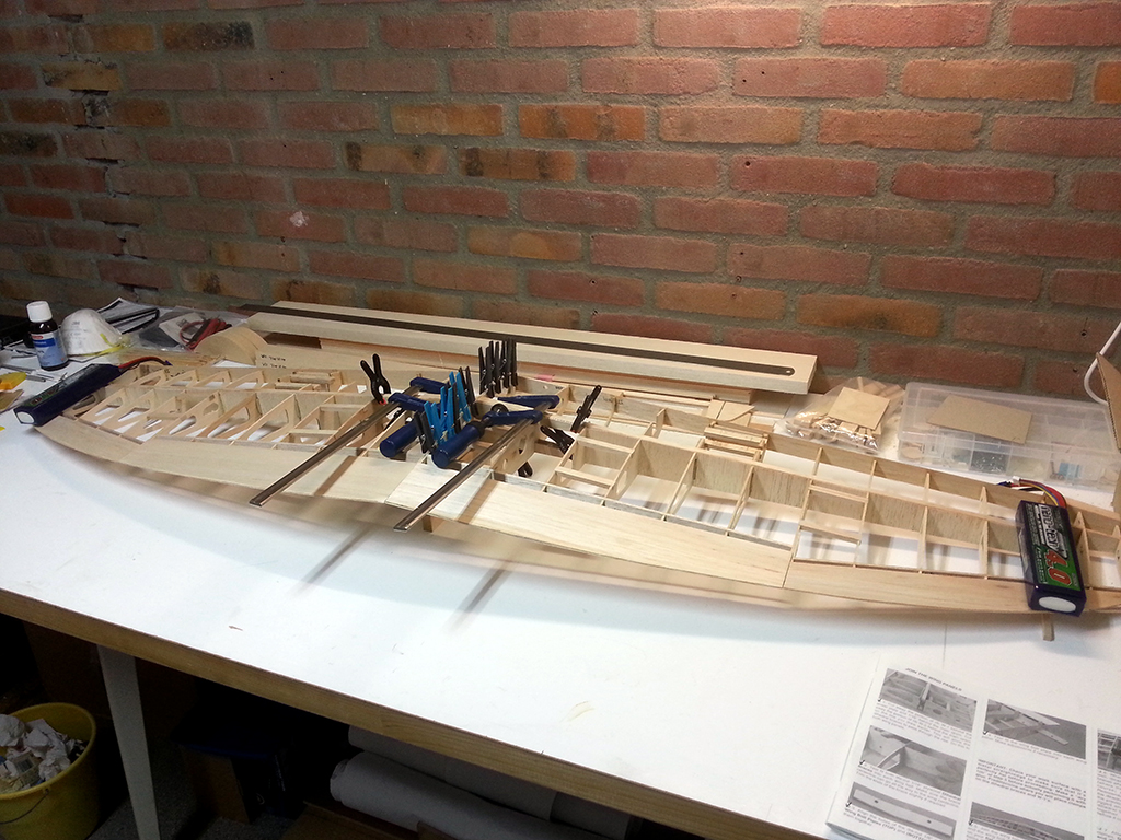
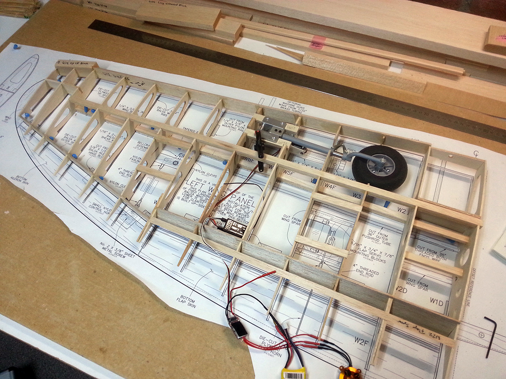
It’s been a while since I’ve updated my website, so here is some progress on the Jug. It will continue to be a (very) slow build though, because I will make room for another ARF inbetween, but first…

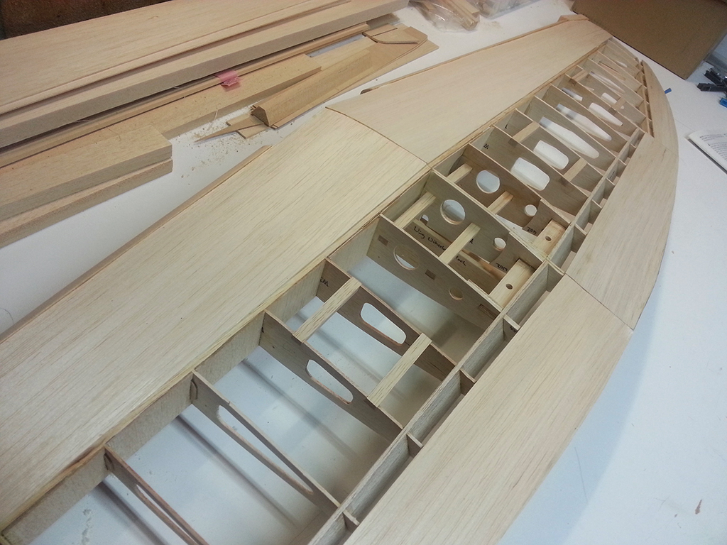
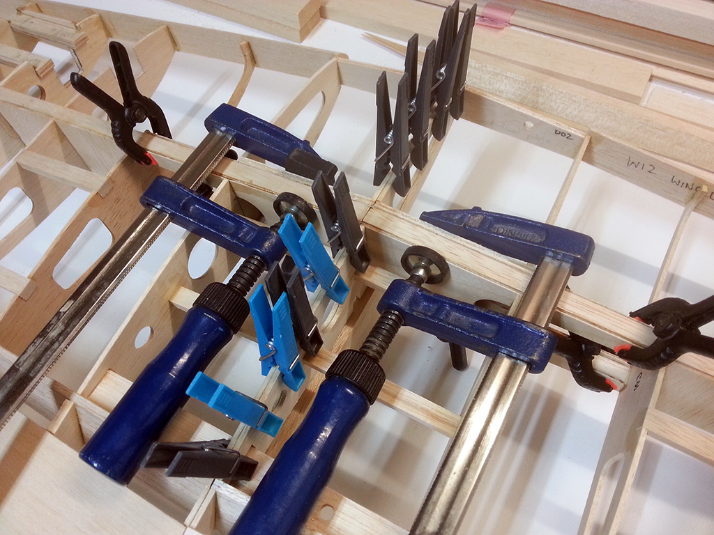
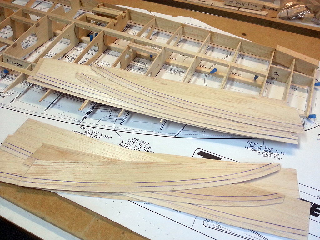
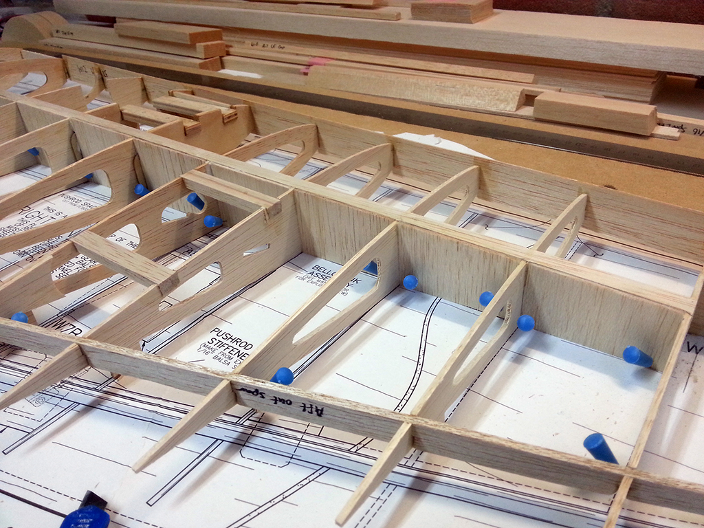
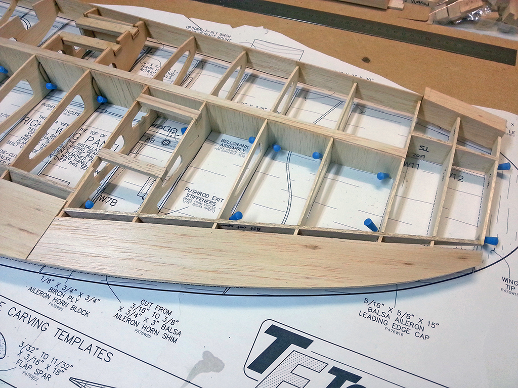
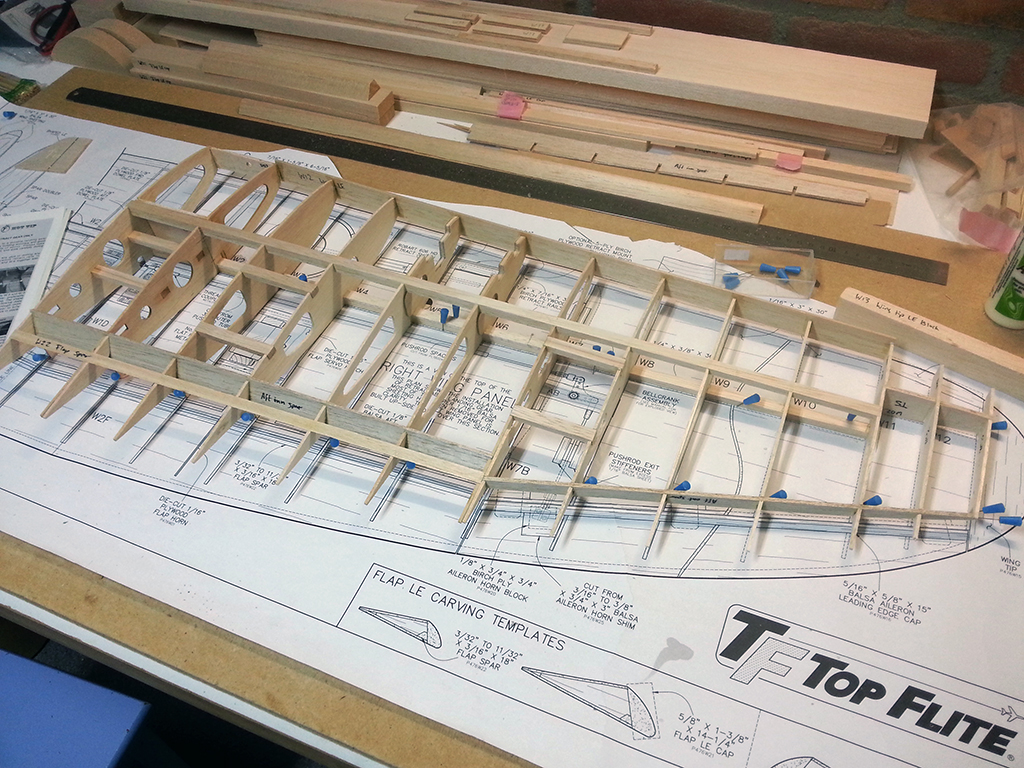
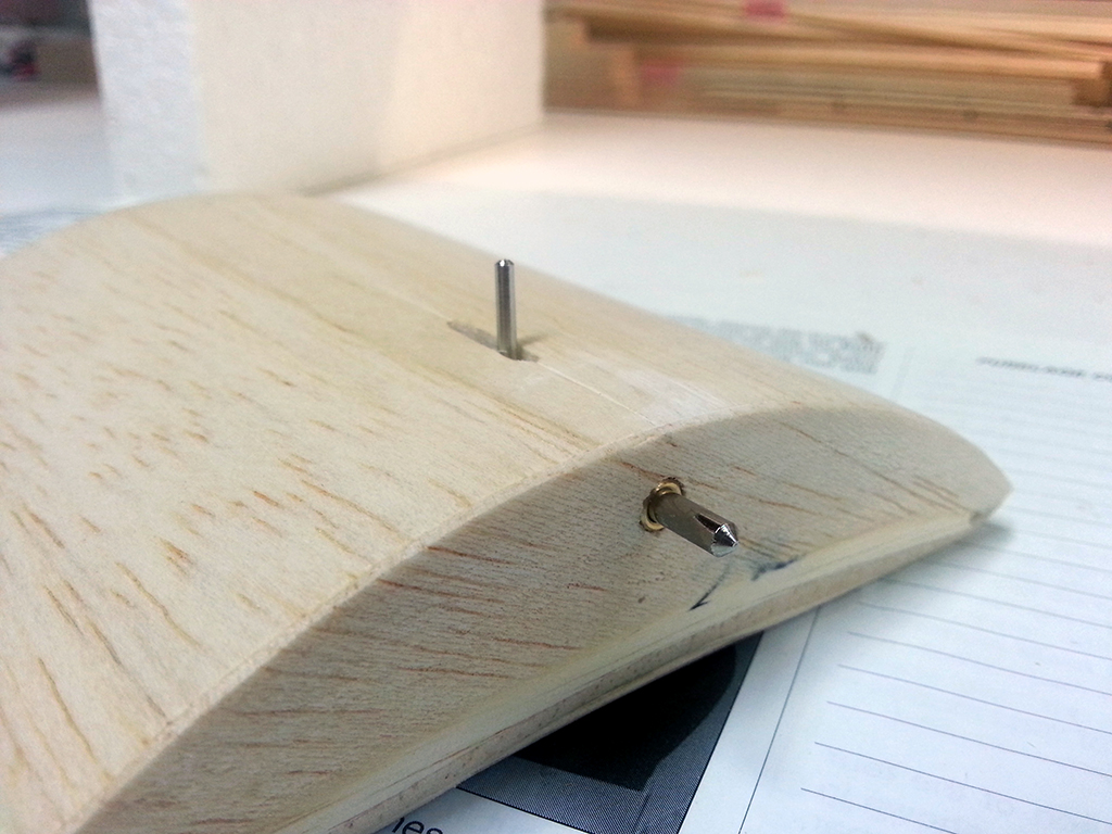
Time to remove the sheeting on the underside of the wing where the servo hatches will come:

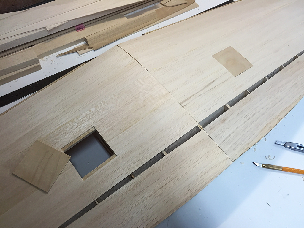
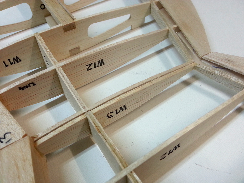
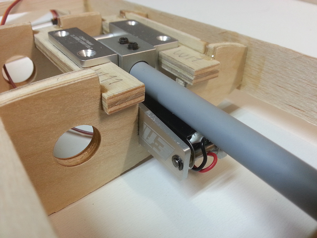
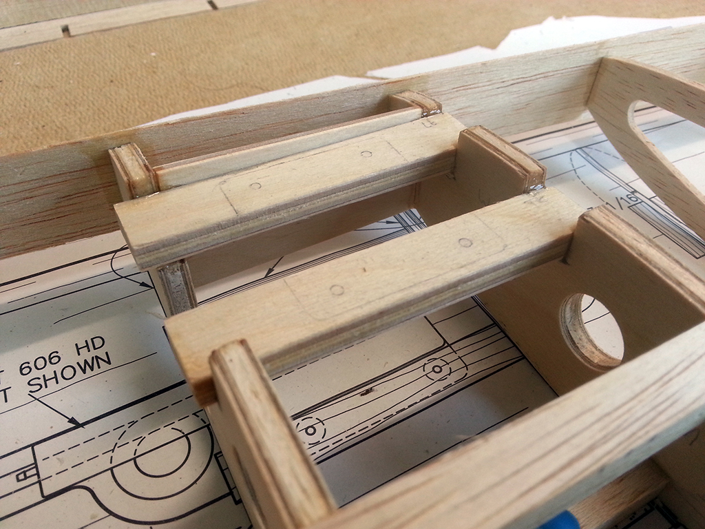
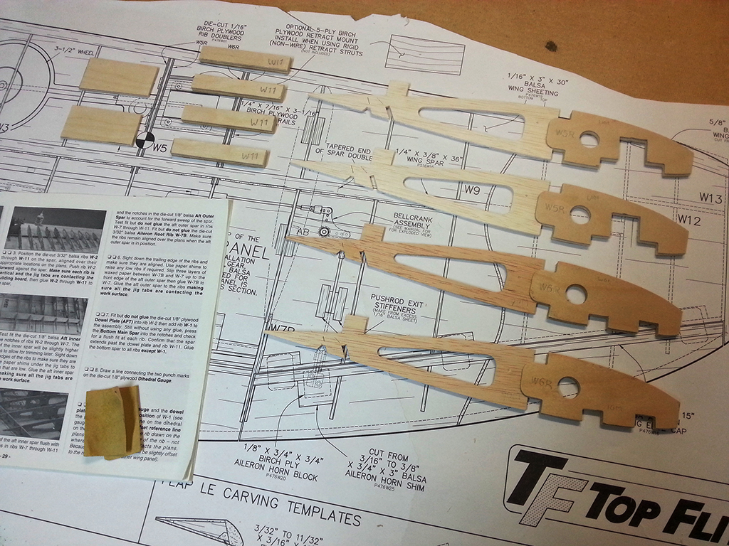
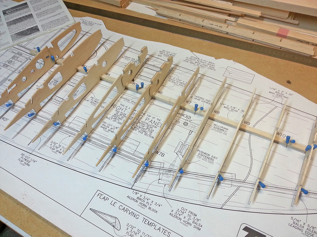
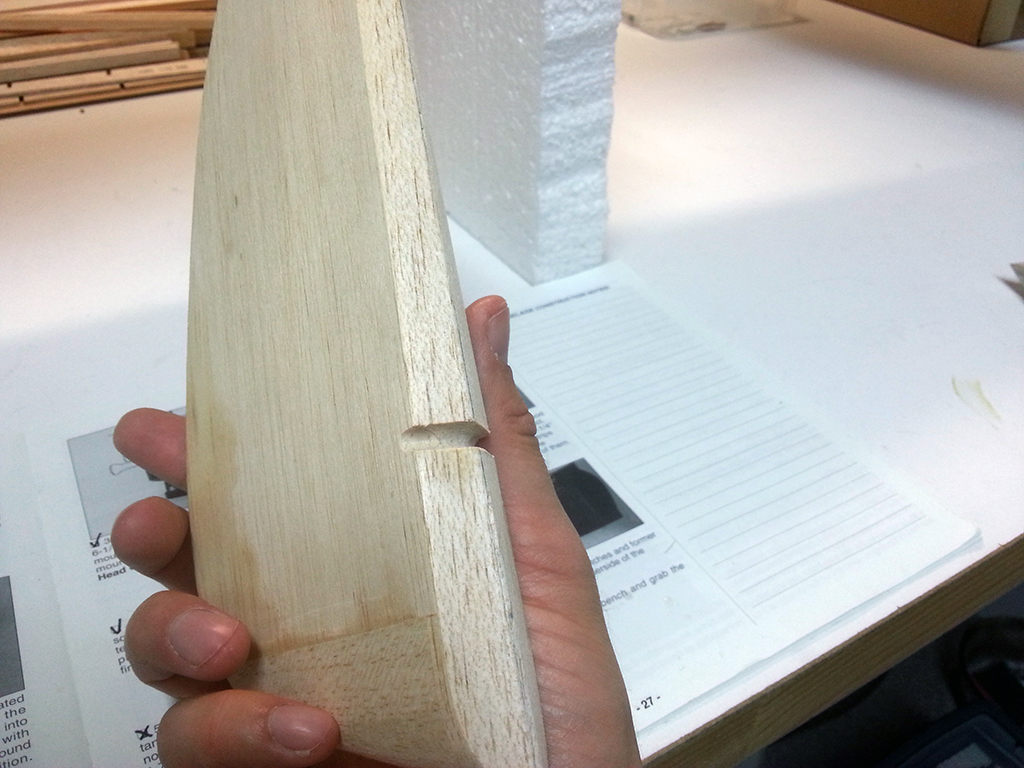
Two hatches (for the flaps) were included in the kit, but I also had to make two of them myself for the ailerons, as I changed the setup to four servo’s. Everything went great, except for the last one. I placed one of the servo rails on the wrong side of my pencil mark, before sheeting the wing. It was a delicate little job to fix this with the balsa sheeting already in place, but with the right tools I managed to cut out the old spar and glue in a new one with damaging the structure or the sheeting (you can see where the old one was in the ribs):

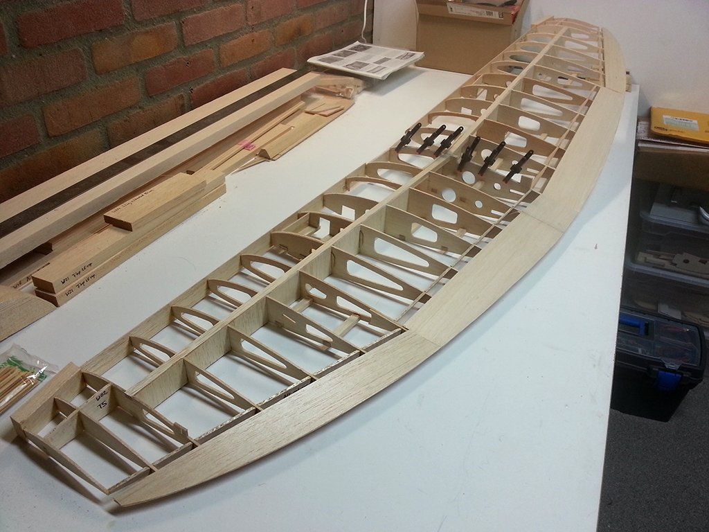
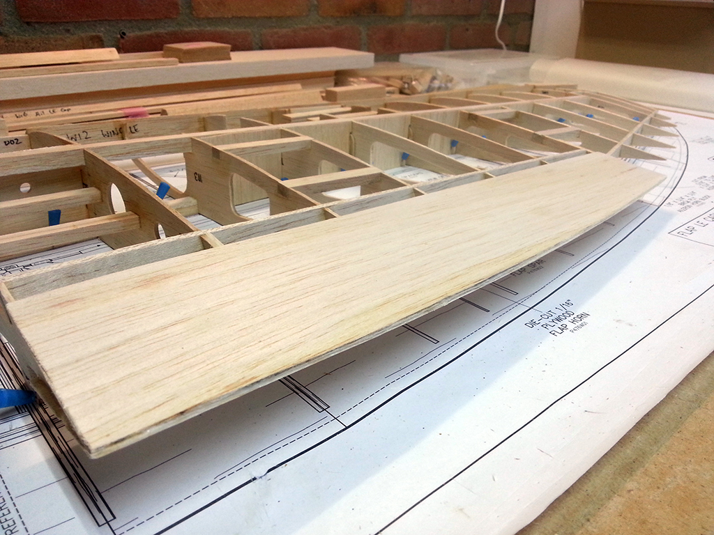
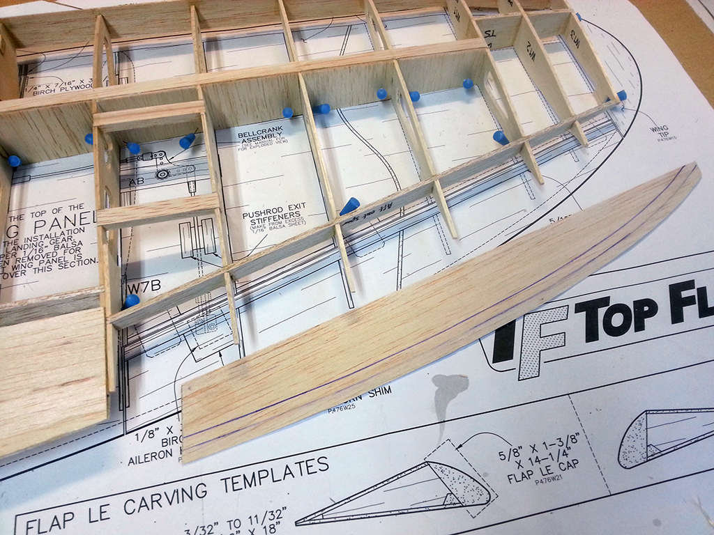
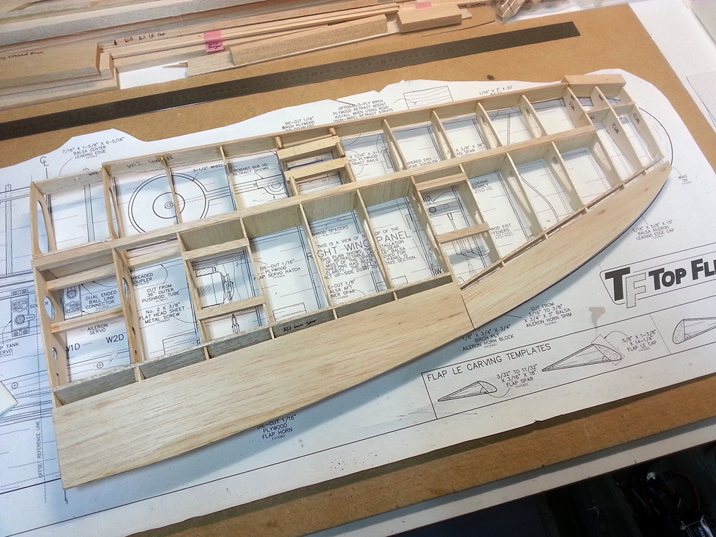
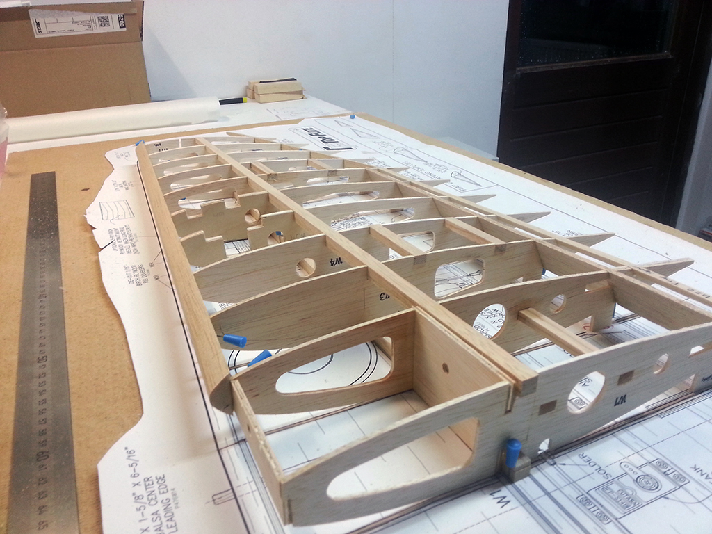
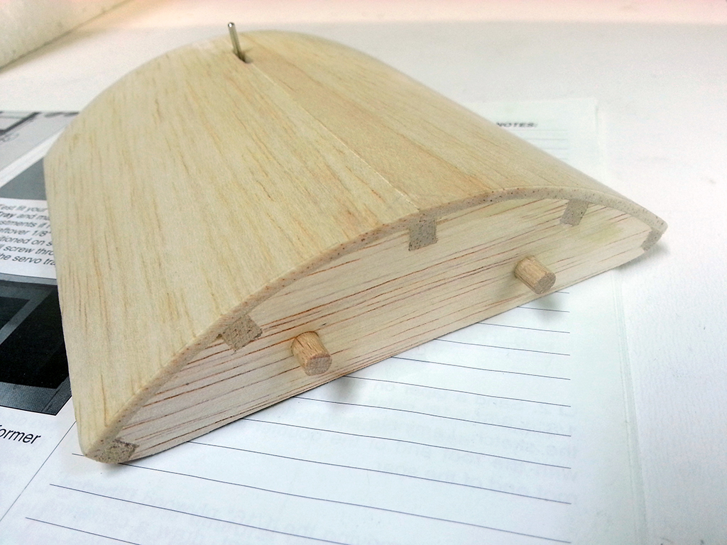
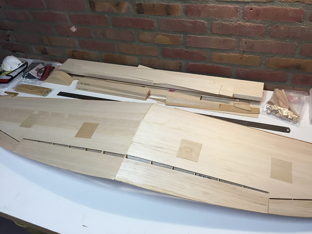
All four hatches are done, great fit too!

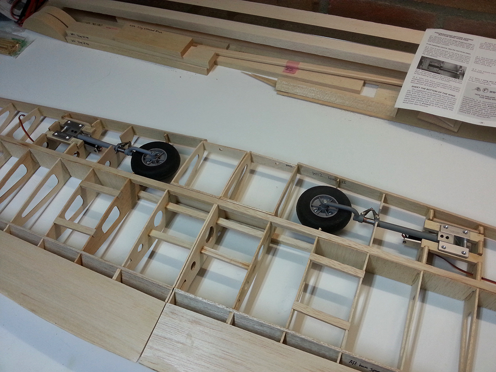
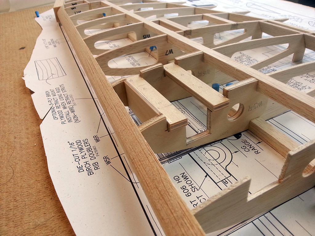
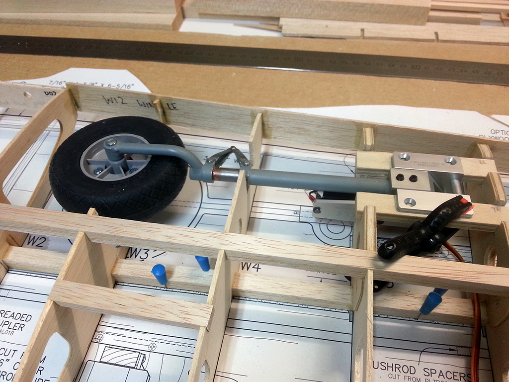
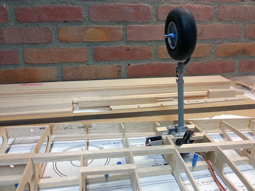
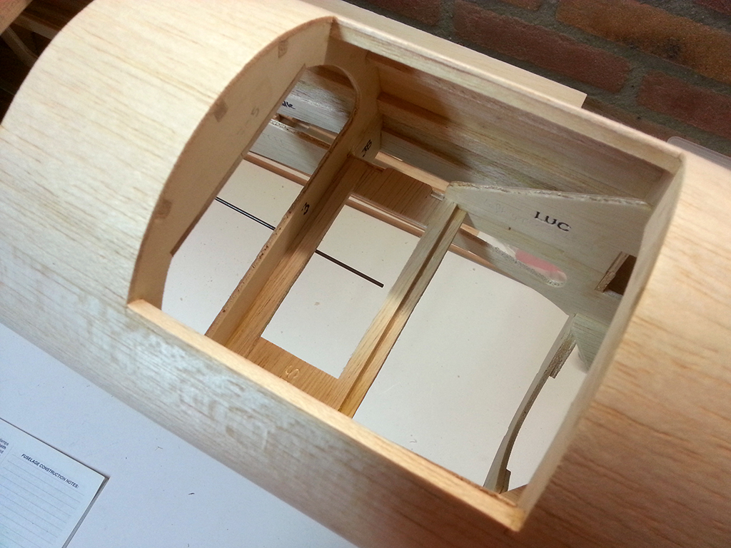
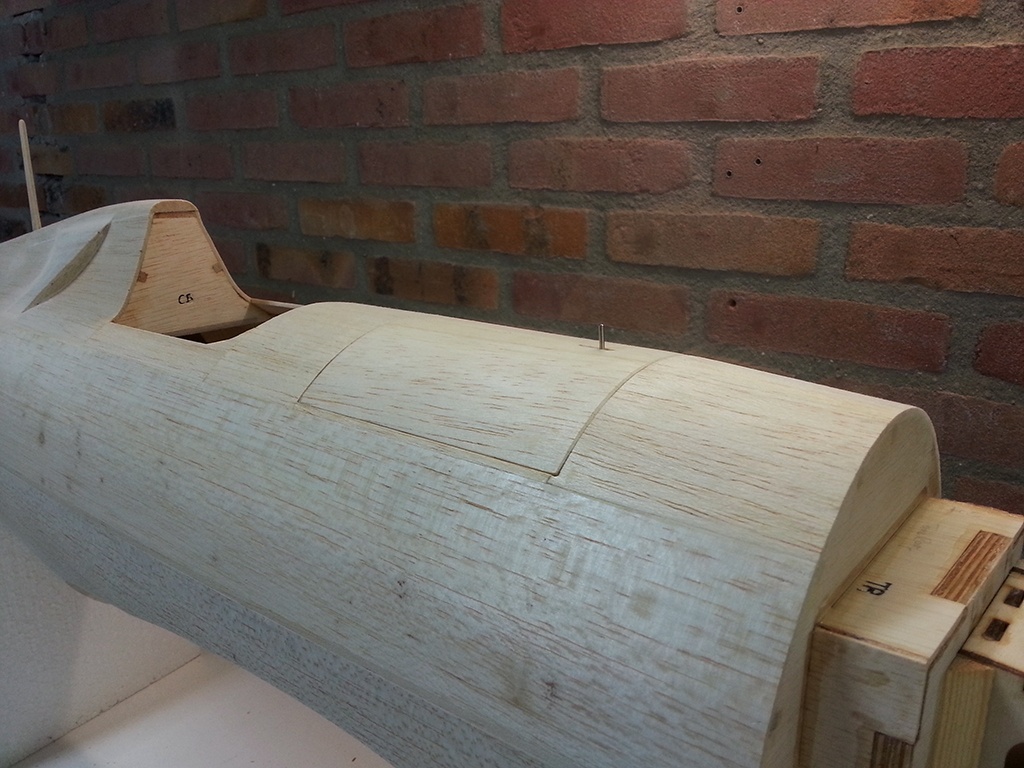
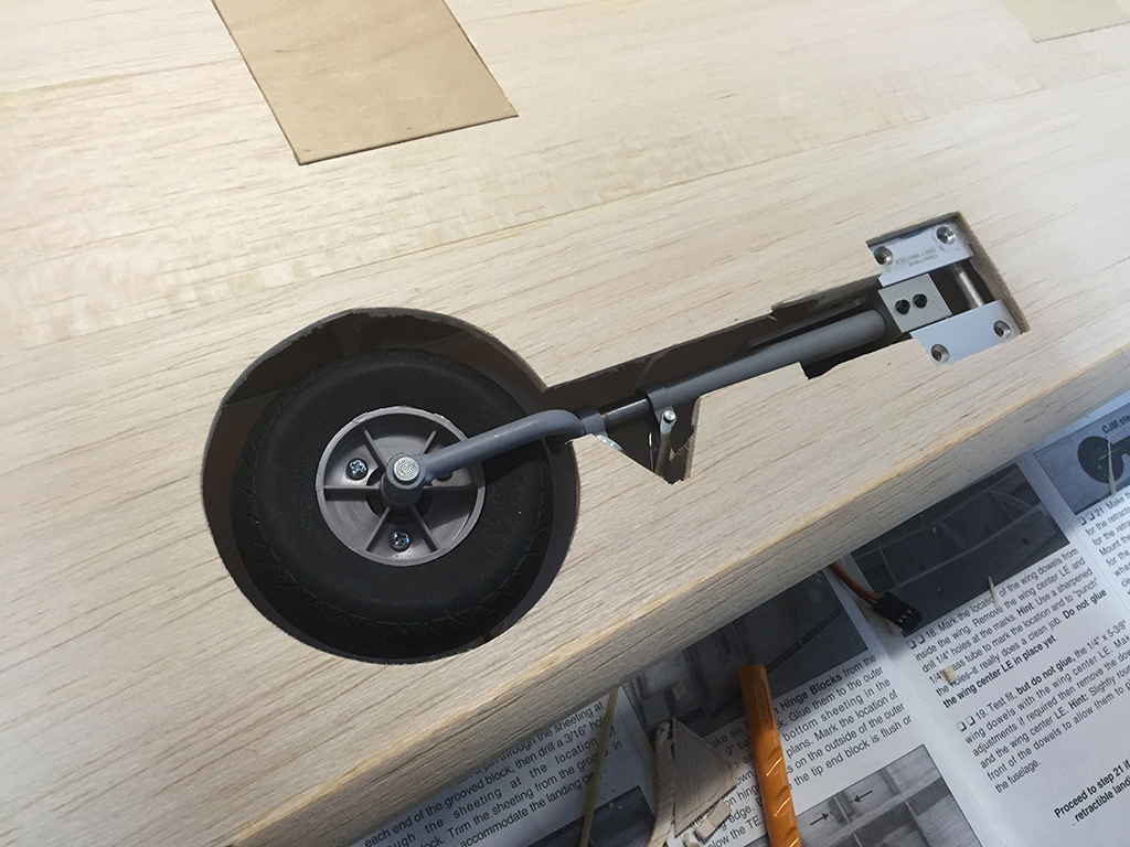
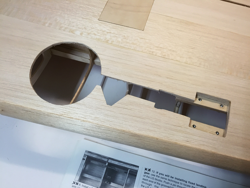
Now onto the cut outs for the wheels. This is how the manual recommends to do it, a kind of minimal cutout without using doors:

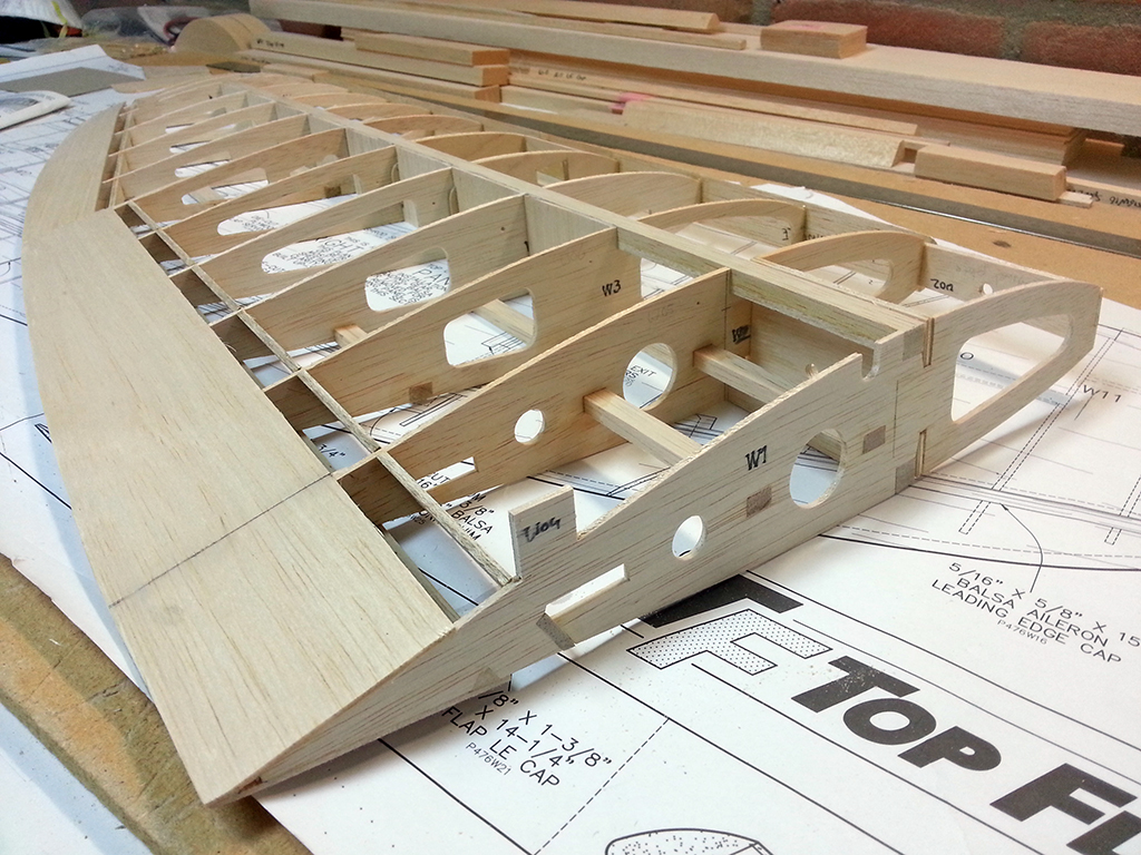
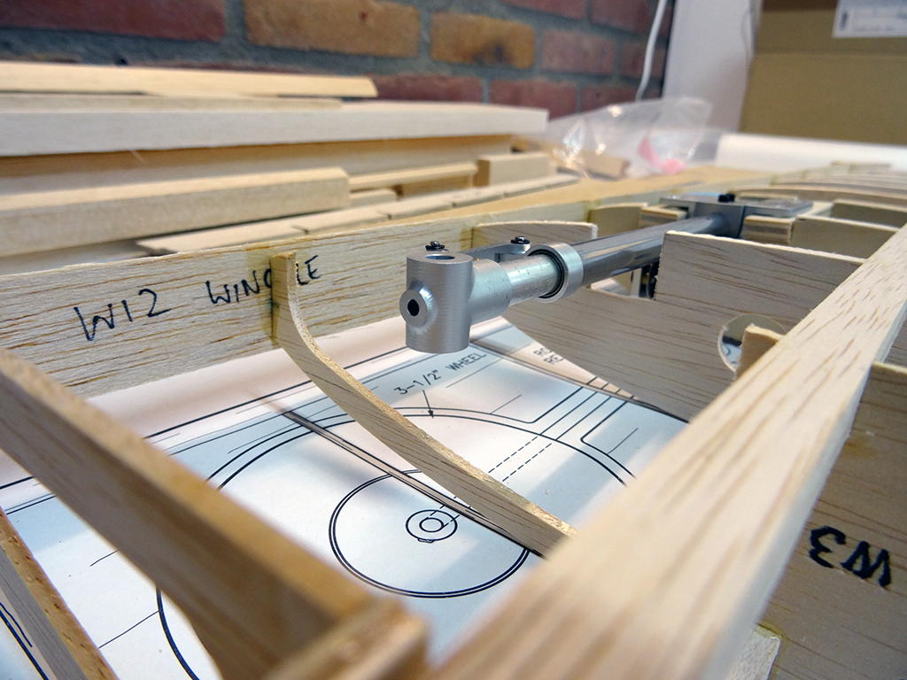
And the second one finished as well:

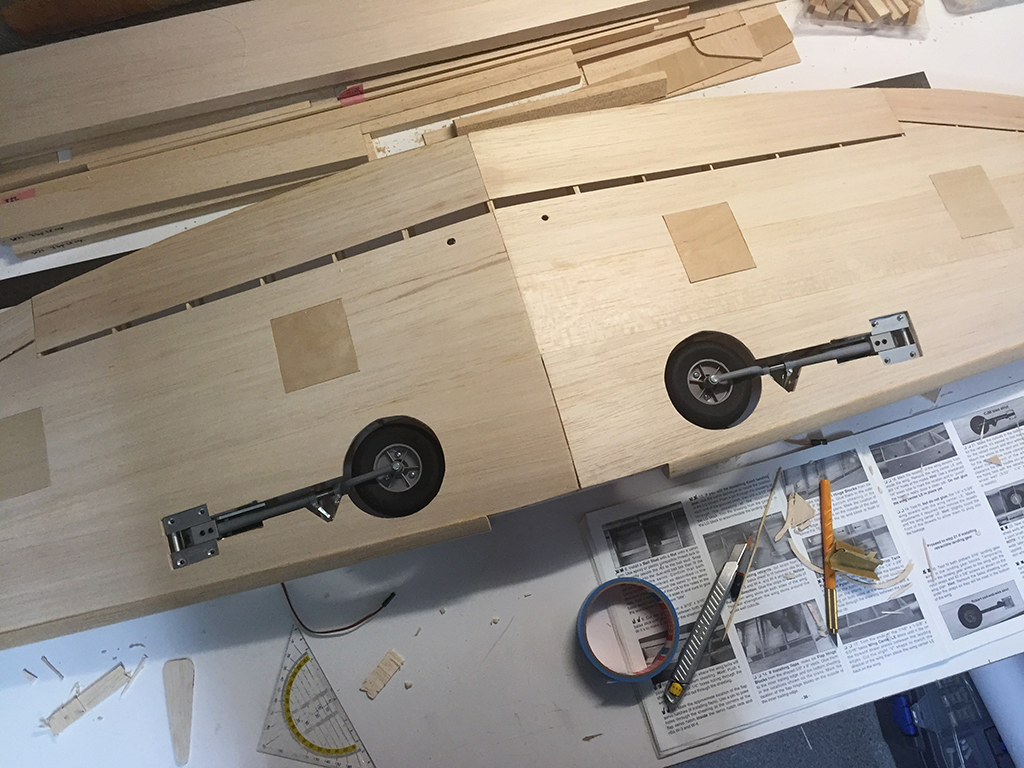
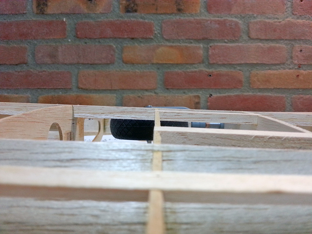
It’s still a rough cut out, but I first need to decide if I go with this route, or add doors to it (then I will need to cut out a larger part of the sheeting to accomodate for the doors). Retracted this is okay, but with the wheels down it will probably not look right without the gear doors…

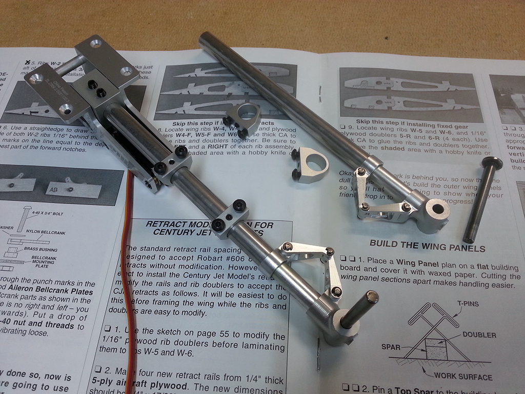
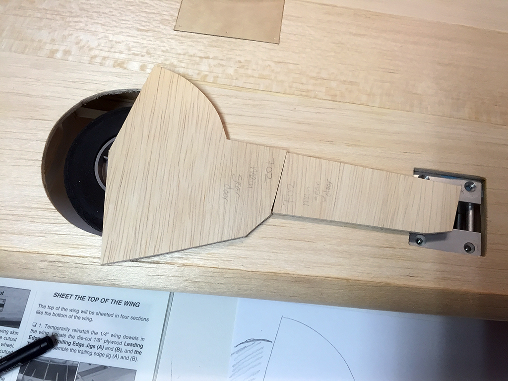
So I took out the doors from the kit, actually intended for the fixed gear and, hence, they will not fit the smaller size of the retracted wheels. The doors are even larger than the space between leading edge and main spar! Next to that, the upper doors are too short:

Back to the drawing board it is! This drawing shows the original doors in pencil and the minimum required area in black pen. But the latter doesn’t look right either, because they deviate a lot from the scale lines. Will need some revisions:

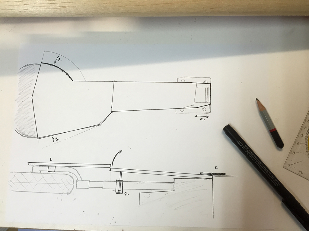
The drawing also shows the mechanism I would like to use. Door 1. will be fixed to the lower leg of the retracts. Door 2. will get a hinge near the base of the legs and will be fixed to the upper leg of the retracts with a wire that is able to rotate. This makes it possible for door 2. to move together with the leg, sliding under door 1. This is a common method, but I will probably still fabricate all parts myself. The doors also shouldn’t be flat, but they need to follow the airfoil shape.

Gear installed, started sheeting

This is getting a slow build more and more, but I’ve got some progress to share again! What you’re seeing here is all work from the last two months, done bit by bit. The retracts required a lot of fiddling and fine tuning and for the rest I got distracted again…

The first stance test, got the landing gear in temporarily and put the recently glued wing halves on their ‘feet’ for the first time:

Here you can see the landing gear assembly in detail, it’s not very scale, but it looks way better than wire gear. And for my semi-scale Jug, they fit the bill:

Looking at the gear up position through the ribs from the top side of the wing. After a lot of fine adjustments, they fit nicely in the wing (but barely):

I then used this little fellas to make the landing gear units removable for maintenance, without wearing out the wood, which would’ve been the case with the suggested Philips screws:

And once mounted, it looks like this:

But the wing got a little surprise waiting for me when I fastened these bolts… apparently, one of the retract mounts (those ply rails) wasn’t in the same plane (geometry-wise) as the other ones and fastening these bolts actually warped the wing drastically on one side. The retracts pulled the rails straight, lifting up the wing tip. This cancelled out all my washout on one side. That’s bad! So first, I again adjusted these retract rails so the installation of the retracts didn’t change the position of the wing. Then, I literally glued the wing to the table. Or actually, I glued the wing tabs on the supplied supports, which I’ve attached to the building table with pins:

This way I am sure that the wing will be held in position during sheeting, with the correct amount of washout. And once the bottom sheeting is on, it won’t warp anymore. I can simply unpin it from my building table and break of the tabs, and I’m good to go! And since the mounting of the retracts didn’t change the wing shape anymore, I’m assured the result will be perfect.

Next step was to glue in some balsa scrap to fill up the empty areas around the retracts, for the balsa skin to rest on:

And finally, after a lot of puzzling and fine adjustments, this is how the finished gear mount looks like. It’s a drop in assembly from now on!

Time to start sheeting, starting with the bottom of the wing, of course. Each wing half is made out of four balsa sheets, butt glued together in pairs before fitting them on the wing. This places the only seam left right on the wing spar, which is an easy place to sand. Because the bend is very shallow, I didn’t use contact glue for these sheets, but my favorite aliphatic glue together with some pins and tape:

Two pairs done, two to go:

And after repeating the same procedure for the aft bottom of the wing, the underside of the wing is now fully sheeted!

I’m pleased with the result, no filler involved yet! With the wing tips on, the final span will be 63″ (~ 160 cm), and with this wing cord that’s quite a large area I must say. Definitely the largest and most complex wing I’ve built to date, but Top Flite really makes the process easy and fool proof. It not only has a dihedral and a round taper, it also has a second spar towards the tips, built-in washout, different airfoils towards the tips and it also tapers in thickness quite a bit. I wouldn’t get my head around this in a scratch build I guess..

Next time I am going to prepare the bottom side of the wing for the top sheeting, which means creating the servo hatches and the landing gear cutouts. After sheeting the top, it’s time to make those control surfaces operational. To be continued!

Joining the wing halves

I’ve spent my time on other priorities last three months, but now it’s time to pick up the build again!

When I finished the second wing half, I found two issues: the wings seemed to be twisted very slightly, introducing less washout than intended, and the retracts weren’t equally aligned, one sat a little deeper than the other one. I wanted to fix both issues before continuing with the build.

To start with the good news, when I turned over the wings, laying them flat on the table with the wing tips touching each other, I noticed the degree of washout was perfectly equal for both wing halfs! You can see the wing tips align perfectly well:

With the building tabs on the table, you can still see they hover about .5 mm above the table, but they are equal in that matter, so it won’t influence the flying characteristics that much. Maybe I can twist them back in position when putting the sheeting on, we’ll see, but anyhow I am satisfied with the result so far.

I then tested then wing halves clamped together with the right amount of dihedral, also a good fit:

For the struts, I had to alter one of the retract mounts, filing it down until the two struts had the same position, depth within the wing and alignment towards each other:

This is a close up of on of the retracts. They sit a little deeper than the plans suggest, but the fit is so tight that it doesn’t weaken the structure:

So with all those details sorted, it was time to join the wing halves. A very exciting task. It took me quite some time to get everything to fit properly, but when it did, gluing was a non-event actually:

Right wing progress

I’ve made a lot of progress on the right wing last week! The day before NYE I’ve pinned the main spar and the ribs on the building board:

And now, a little over a week later, I’m almost at the point that I can join the wing halves. I only need to add the sheeting of the control surfaces and the shear webs. Tonight I glued the retract rails in place:

Looks like the retract fits even better than the first one: it goes in almost completely when retracted! It’s only a matter of tenths of a millimeter, but this proves it’s possible to get it in completely. When everything still works out like this when the glue is cured, I’m going to adjust the other side again to get them both to fit like this.

Too bad I discoved one of the Robart wheels is almost unusable.. a bit of a disappointment for such a quality brand. It’s completely misshaped and so it doesn’t track well. It even touches the strut in two places. Think I need to order another set.

And today, all the way from Illinois, this arrived. It was well packed, delivered within two weeks (I ordered it on boxing day) and shipping was only $2!

I ordered this cowl because it’s from fiberglass, it’s finished and already painted. The cowl in the kit is from ABS plastic and consists of three parts. You need to cut those parts free and glue them together. And the checkered pattern is difficult to paint well, or at least time consuming. I think the quality of this ARF-version cowl is reasonable and it fits quite well, so I think I’m going to use this one. Although I will probably still try to build the one from the kit, so I can decide on the end result (and weight) of both cowls.

Left wing structure finished

Now I’ve resolved the retract installation issue I was able to finish up the structure of the left wing fairly quick. First, I’ve glued in the shear web for the retract (rails) which you can see here:

And this picture shows the completed retract mount and cutout rather well, you can see there’s not much left of the rib the retract’s sitting in, but nonetheless it’s still quite strong:

Time to prepare the control surfaces sheeting for the wing. I had to make four aileron sheets, two upper flap and two lower flap sheets. They are cut out from stock 1/16″ balsa using the patterns provided on the plans and then the edges are beveled so they could be joined at the trailing edges. The first line on each sheet indicates the bevel and the second one marks the end of the ribs:

Then I cut and added the shear webs to the back side of the main spars:

And sheeted the flap:

Sheeting the control surfaces isn’t difficult but you need to come up with a technique to hold the sheeting in place while the glue is curing (since I’m not using CA whenever I can). First, I’ll check how the sheeting should be fitted:

Then I use aliphatic resin (white wood glue) to glue on the upper aileron skin (the wing is upside down on the building board). I use packaging material which is quite spongy to hold the sheeting in place, when pressed under the wing, this will press up the sheeting against the ribs. Of course, doing so would lift the wing of the building board so I need the weight of a few batteries to hold the wing down:

Might not look very professional, but it sure works! The lower sheeting is glued with the same glue and held in place with pins and batteries while curing, here’s the end result:

Which means I’ve finished the structure of the left wing, so I’ve removed it from the building board:

After trimming off the tabs (except W1 and W11) and sanding both the spars and the sheeting flush with the root rib, I could turn it around and clean it up:

Time to clean off the building board and pin down the plans of the other half of the wing and repeat all steps, which should go faster as all prep work is done already. As we speak the ribs of the right wing are curing being glued to the upper spar already.

Retract fitting take two

And I’m back at the Jug again…! I received the new struts and wheels a few weeks ago, just didn’t have the time to work on the plane and I also got distracted by some side projects.

The new gear, Robart 3/8″ offset RoboStruts with Robart diamond thread wheels (3-1/4″):

Unfortunately, after puzzling everything together I found out this setup also didn’t fully retract into the wing – the struts were protruding on the bottom instead of through the top of the wing. I spent a few nights measuring and tweaking and came to the conclusion I had to rotate the retract rails a bit to get the retracts and wheels to sit a little deeper into the wing. Lowering them wasn’t an option, because that would weaken the structure of the wing too much. Still, the struts stick out a tad but that’s something I can live with (or something I have to live with I guess). Also, because I’ve tilted the whole assembly by two degrees, I’ve created a positive camber in the wheel stance. It’s the best compromise I could come up with and in the end the wings just aren’t thick enough for retractable scale struts and wheels, certainly not with the wheels retracting before the main spar (the actual scale location would be further back where the wing is thicker, but that would require you to cut through the main spars and this would complicate the build even more). Anyhow, I’m happy with how it turned out. These struts and wheels are going to look great (even more if I can get the doors to fit as well later on). Here you can see the gear retracted in the wing:

And this is with the gear out. It’s hard to see but the struts should sit at 85 degrees because of the 5 degree dihedral, but due to my altered setup they are positioned at 83 degrees when lowered. Furthermore, alignment is spot on:

And here you can see how the struts still protrude a little (note that the balsa wing sheeting still has to go on):

I have made a little vid to show the retracts in action from different angles:

When I was satisfied with the setup, I glued the rails in place with 30-minute epoxy. Now I can finally continue with the rest of the wing (mostly sheeting), before starting with the other half. Final assembly of the retracts will be done when both wing halves are finished and joined, so I can align the struts (equal camber, toe-in / tracking and general aligment such as height and forward angle).

Left wing structure

In the past two weeks I spent a few evenings to finish up the wing structure of the left wing. Despite the complexity of the wing structure, it goes together quickly and almost effortless. You can see I’ve added a bottom main spar, leading edges, multiple aft spars (flaps, ailerons and inner spar), the outer wing tip structure and multiple servo hatch supports. By the way, I changed the way the ailerons are controlled: the plans suggest one central aileron servo with push rods and bell cranks, but this hard to adjust later on and also prone to result in a sloppy control mechanism, causing flutter far more easily than with a short rod and a direct connection between servo and control. So I added two servo hatch supports where the aileron servo will go and dropped the whole push rod and bell crank construction. A lot easier to build too. Here’s the wing structure almost finished:

And from another angle:

Then I cut out some rib material and placed the retract rails to test fit the retracts and struts. It looks like it fits in very well but there’s a problem:

As you can see in the following photo, there’s not enough clearance for the wheels, which are 3-1/2″ high and 1″ thick:

I tried to play with the tracking of the wheels and rotated the strut upward a bit, but I still cannot get enough room under the strut for the wheels to fit in. I find it strange, because these struts look a lot like the ones suggested in the manual – they even say you might be able to fit a 3-3/4″ wheel in there… – but long story short, this isn’t going to fit.

The original full scale struts have an offset, where the center of the wheel is aligned with the center of the strut. I initially bought these straight struts because they look like what the manual suggests, they are called ‘P-47 Struts’ and they fit the retracts I chose, being from the same manufacturer. Now I think I should look out for offset struts, because they give me more play and as a bonus, they resemble the full scale struts a lot better. So I returned the straight struts and ordered Offset RoboStruts instead (thanks Aerobertics.be for the great service!)…

Although I cannot continue with the current building step of installing the retract rails, I may be able to do some more things further down the list, like skinning the control surfaces and installing the shear webs. To be continued!

Starting with the wings

I had to wait for the retracts to arrive before I could start with the wings. Luckily this didn’t take long and last week I received my order. It’s a set of 85-degrees 60-120 sized retracts with a pair of matching oleo struts from E-flite. E-flite calls them P-47 struts, probably because they fit their Hangar 9 Jug, but they do not resemble the real ones all that much.. which isn’t a problem for my semi-scale build, even more because they look very nice and of course, a lot better than wire struts:

Before starting building up the wing structure, next to some general prep work, I had to modify a number of parts to fit these specific retracts. Most modifications are mentioned in the build instructions, but I had to pick only some of them and I also needed to modify the rib cutout for the retract mechanism, as I use servoless retracts that didn’t exist when these plans were drawn:

Once that was done, the structure of the left wing arose very quickly on the building board:

Nice to see how all those ribs line up, floating above the plans due to the building tabs:

I would have liked building both wings simultaneously, but I do not have enough room for that, so I have to build them one at a time, but I think this could go very fast from here nonetheless.

Finished the fuselage

Last week I finally got the time to finish up the fuselage!

I’ve mounted the firewall and the motor mount. Went together very well. Because of the right and down thrust angles, you cannot just center the motor mount on the firewall and my mounting points did not match those of the plans. So I aligned the motor mount using CAD drawings I’ve made. Seemed like a daunting task, but it wasn’t:

Then I recessed the rudder for the elevator joiner wire. Not mentioned in the instructions or on the plans, but a very obvious step needed to make the rudder and elevator fit together:

So I finally could test fit and assemble the tail and check the controls throws of the elevator. Looking good:

Then I buit and installed the fuselage antenna, just behind the cockpit, from 1/8″ birch ply. It’s remarkable what such a small detail does to the overall appearance of the plane:

… installed the servo tray:

And finished the battery hatch! This was a small little puzzle on its own, but I managed to get everything sorted and I’m very pleased with the result. First I’ve installed a canopy latch on the front side of the hatch:

Then, I glued some wooden dowels into the other side of the hatch:

After drilling the corresponding holes in the fuse itself, the hatch fits snugly into the fuselage opening and there’s absolutely no play at all. A nice and clean installation:

And last but not least: the pin of the canopy latch is in the right location to represent the front antenna on the fuse of the Jug! So it’s scale too :-)

By the way, I’m not sure if I can do the checkered pattern on the cowl, but if so the Snafu absolutely is my first choice to replicate visually.

Motor mount

After cutting a prototype by hand I’ve changed the design of the motor mount slightly. The sides are cut out differently to save some weight and I’ve removed the cooling holes in the front for more strength. Also, the offset turned out to be too large and was reduced from 80 to 74.5 mm. Then I found that hand cutting didn’t deliver the results I’d hoped for and the plywood from the DIY-store wasn’t good enough (too much voids and hard to get clean cuts). So I decided to order my parts laser cut, which was easy because the design was made in CAD in the first place. I’ve added the motor brand and type engraved in the front, not only because it looks cool, but mostly because the front plates are the only parts where it’s difficult to tell which side is up.

Yesterday I received the parts cut by Laserbeest, only one day after placing my order! Looks good doesn’t it?

Because my design is interlocking, it doesn’t need glue to stay together in the direction of the pull of the prop, which lessens the change of ripping off the motor on a sudden throttle increase when a glue joints fails. All parts only fit in one way too, to make it fool proof to assemble. The exact offset for this application and the added one degree downthrust (I know this motor has way more torque than the adviced two- or four stroke engine as designed by Top Flite) make it a breeze to install. I hope the tapered design adds to supporting the relatively heavy and large motor.

Here’s a dry fit of all parts, which went together like a dream:

I really enjoyed the process of designing my own parts, maybe I’ll design a complete airframe in the (near) future… this tastes like more! Now find some time to assemble and install this mount and continue building the Jug :-).