Maiden flight

As mentioned in my previous post, the maiden flight of the Christen was great! It tracks like it flies on rails and it didn’t need a single click of trim! Also, the CG seemed to be spot on right away with the batteries all the way back on the tray. Had a slightly bumpy landing on the first try, but I couldn’t be happier with how this maiden went! I have a few pictures of the maiden flight I’d like to share, thanks to my fellow club mate Frans.

Waiting in the pit, ready for takeoff:

Coming out of a looping:

Some more in-flight shots:

It has a beautiful presence in the air:

Bringing her back in:

And a happy post-maiden photo to conclude this build:

I really could recommend Hangar 9, as the plane was easy to build with only some minor issues, but more importantly it flies superb. Having advised control throws and expo settings in both low and high rates is an amazing help too. Of course, you could fine tune anything to your liking, but it’s reassuring to have a well flying basic setup to start with. Also, in retrospect, having chosen for an electric setup paid off as well, as it’s easy to install, start and fly. But it turned out to be very powerful too. So it’s clean, simple and with this size of motor and prop it doesn’t even sound bad either.

Looks like I have a new favorite plane in my hangar!

A successful maiden!

Just a quick post to tell it flies superb! Today the Christen Eagle flew its maiden and it’s so smooth, docile and powerful at the same time! The plane tracks beautifully and is easier to fly than I thought. Only flew in low rate though. I did four flights today and already got to some basic aerobatics like loops, rolls, Hammerheads and a half Cuban Eight. The Power 90 really is sufficient, you can fly just over half throttle and on full throttle it seems to climb forever. Great for very large loops and Hammerheads. The only challenge is landing… the Eagle comes in very well and steady like a rock, but you should be aware of the Multiple Landing Syndrome. My first landing was good for a first, but ended up bouncy nonetheless. Second one was spot on, third had a small bounce as well and the fourth was okay.

I will post some pictures of the maiden once I’ll receive them from a club mate.

Flight preparation

Yesterday I’ve checked the CG once again and it still seems to be just fine with the batteries all the way back on the tray. On the given center of gravity, the plane seems to point its nose very slightly downwards, but I’d rather see this than leaning to tail heavy and they’ve given a range that should be okay around the marked CG of almost 1/4″ either way. I’ve also used all standard / adviced components, so all in all this should be it.

I saved the following step in the building process for last, because I wanted to know where the batteries had to go for the correct center of gravity. Now I know where to place them, so I could install the hook and loop tape on both batteries and tray, to prevent the batteries from sliding back and forth. I also had to enlarge the recesses on the front side of the tray, because the batteries were too short to make it up to the stock recesses. With my latest additions and adjustments, the batteries can be strapped in safely and very tight:

And finally, I got to setting up the control throws, dual rates and expo. I set up the high and low rate control throws per manual, together with the expo settings mentioned on the website of Hangar 9. I defined one switch for all surfaces, so I can toggle between the two modes with the flick of a switch:

I’m planning to take off on low rates, especially because of the sensitivity of the tail wheel / rudder. If this is not enough, I can always switch to high rates, but as I’ve read in multiple reviews, the plane should fly relatively calm and easy on the low rate settings, which is a good thing for a maiden flight. I really hope to fly the plane on Saturday.

I’ll keep you posted!

Finished!

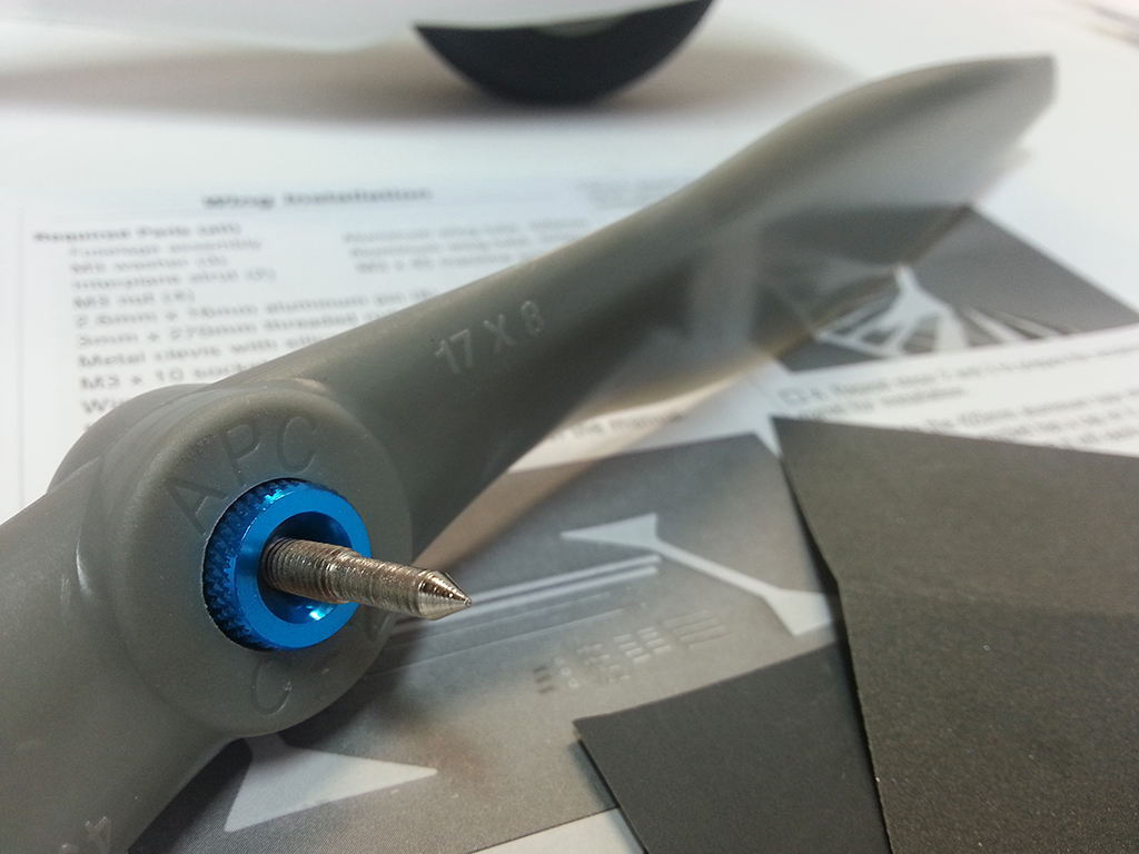
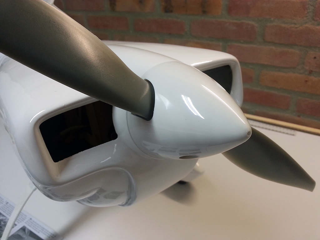
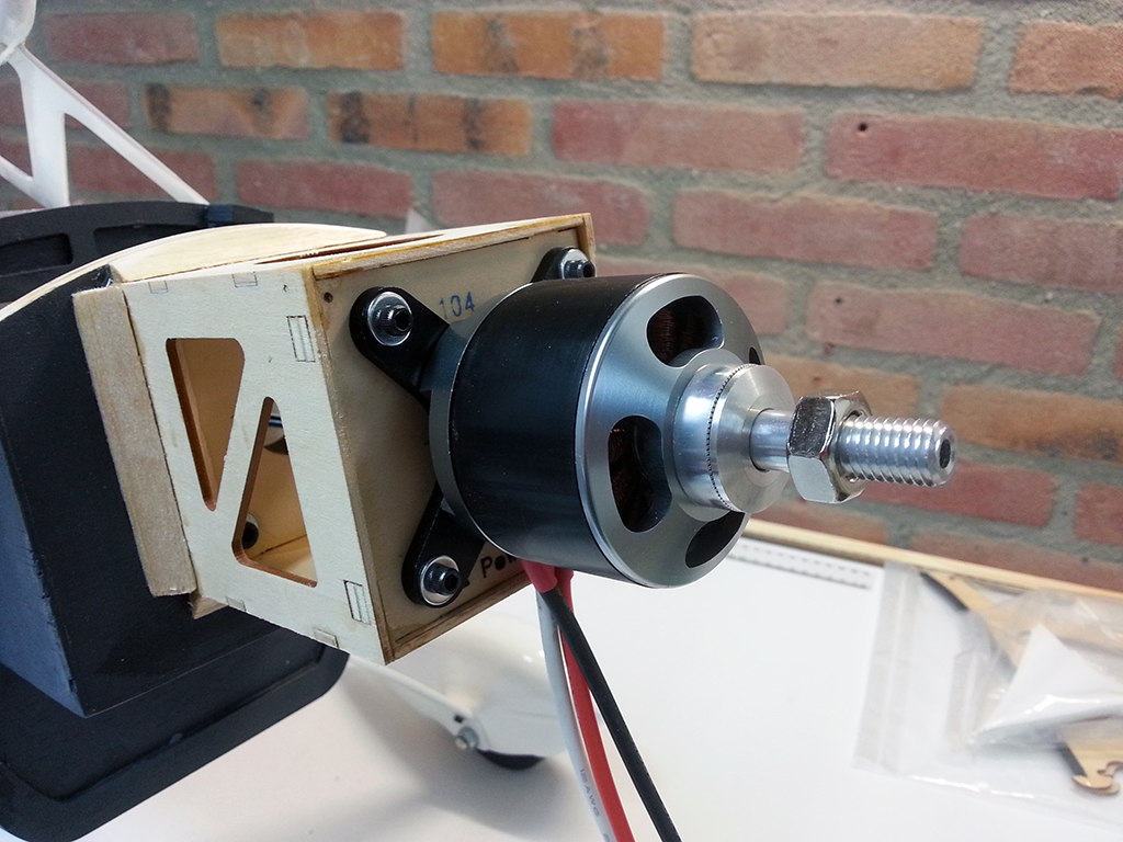
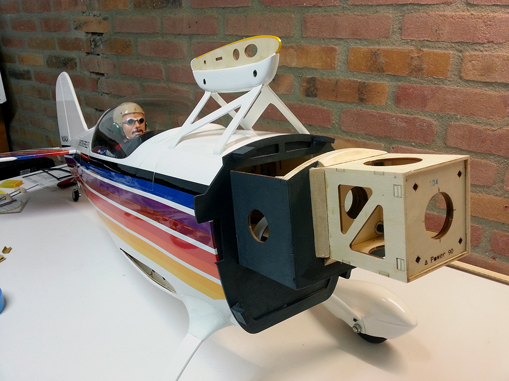
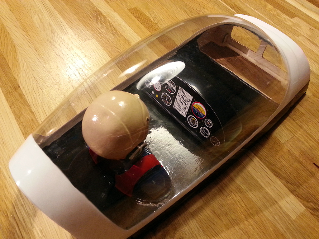
After a little tweaking and fine tuning the hole in the spinner back plate, I got it nearly perfect. The plane doesn’t vibrate anymore up to at least 75% throttle. On full throttle, there’s some slight vibration, but nothing serious. I might need to balance the spinner cone as well though.

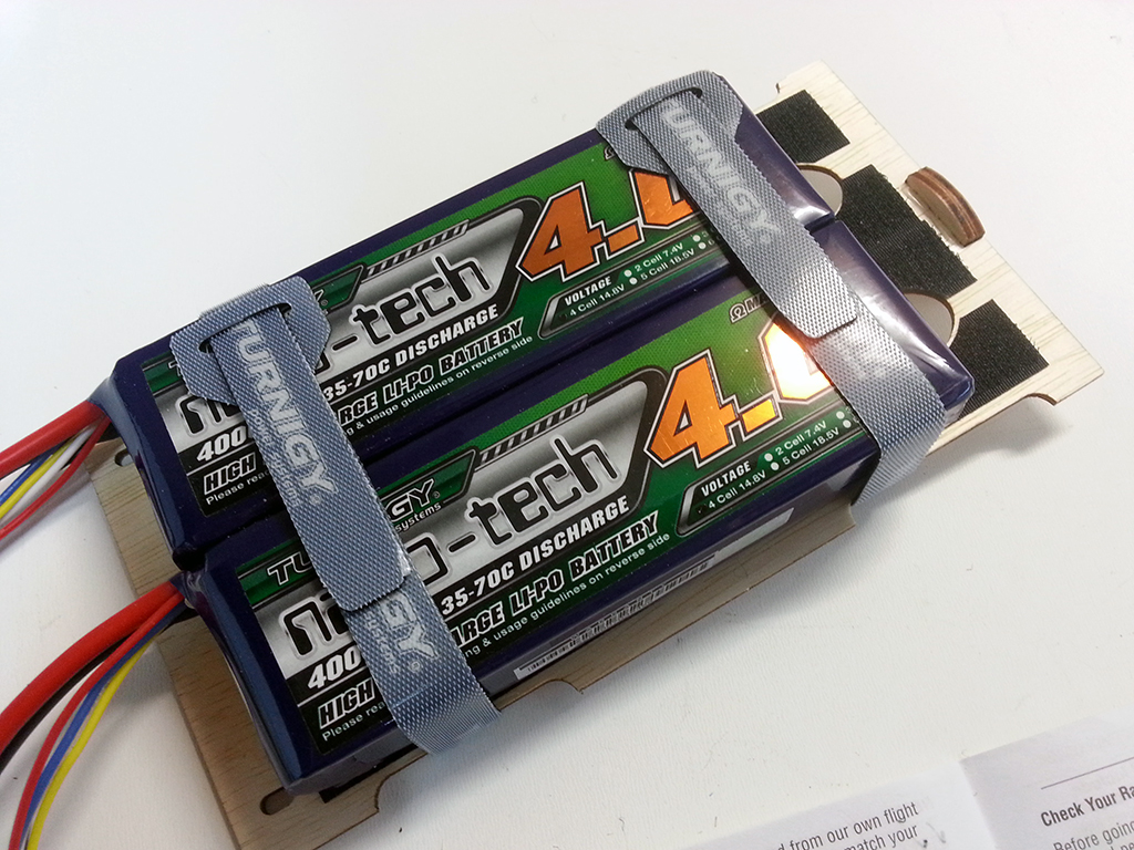
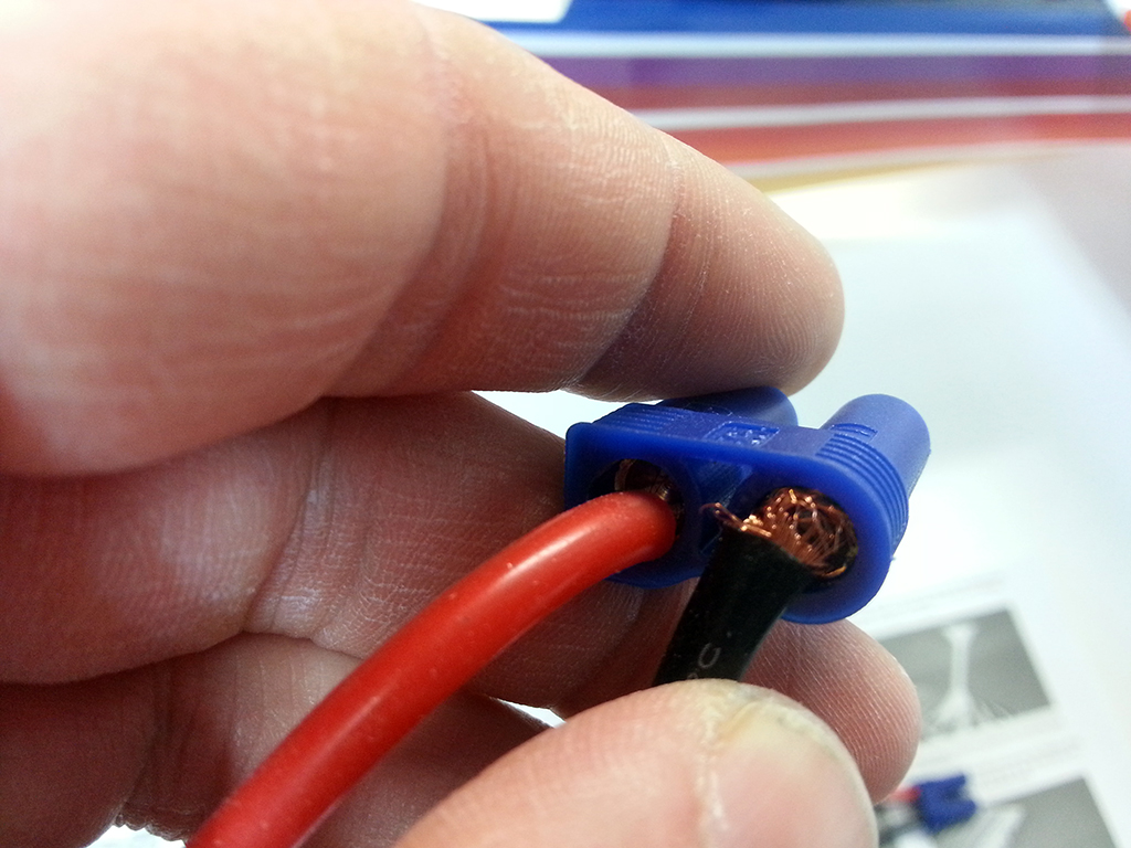
But first, I wanted to finish the last steps of the build. One thing that was bothering me, was a bad solder joint in the battery harness for series packs I bought. I didn’t feel I could thrust these joints and after a little fiddling my suspicions were confirmed:

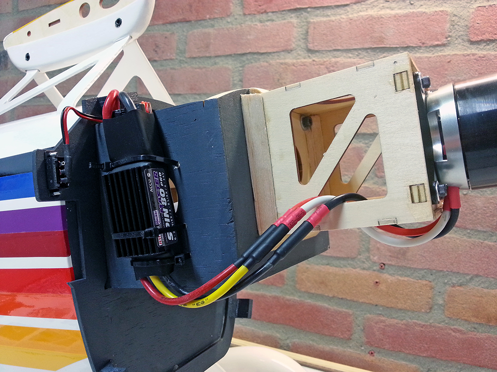
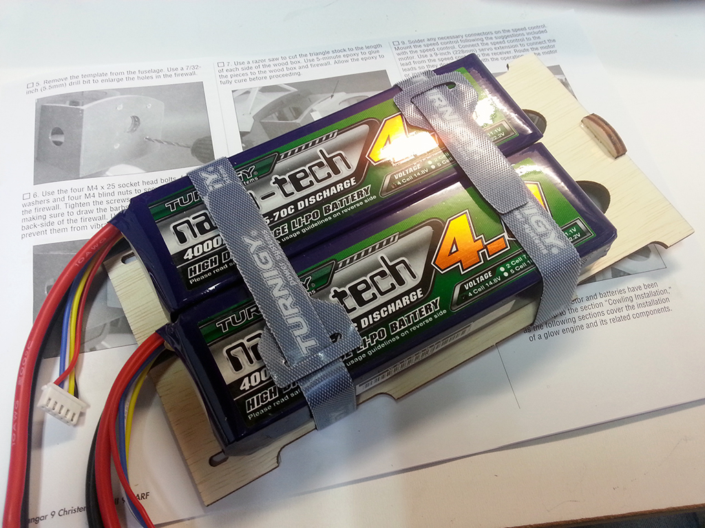
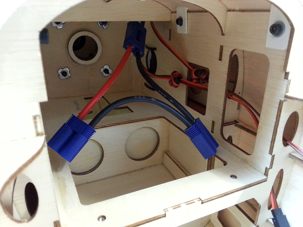
So I ordered a few more parts and made myself a new one with solder joints I could rely on. It’s also a little larger, so I could more easily reach the connectors when installing the batteries:

And then, I only had to install the wings and connect the ailerons of the bottom and upper wing panels. Per instructions I needed to slide them in, secure them with three machine screws (each bottom wing has one and the upper wings are connected with a screw too) and connect the servo cables of the ailerons to the receiver. But I was in for an unpleasant surprise. When screwing in one of the machine screws, which has to go in a pre-installed blind nut, the screw got stuck a little. I was sure I got it perpendicular to the surface in both directions so I continued with some more force applied. Then, it got stuck completely and the blind nut came loose, starting to turn with the screw.. this is bad. I couldn’t see or reach the blind nut, as it was pre-installed in a now hidden spot. I couldn’t reach it with pliers or so and there was no way the screw wanted to loosen up.

I tried a lot of things to get it out. I had to. The screw wasn’t fastened completely, but my wing was on… so this way I couldn’t transport the plane and I couldn’t fly it… I tried to drill the screw out, but the drill bit hardly made a dent in the hardened steel of the machine screw. The only solution I saw to literally save my plane was to cut the head off of the screw using a grinding disk and my Dremel tool.

The grinding made a mess inside my fuselage, but eventually, the head came off and the blind nut fell out. But I couldn’t prevent the washer from getting launched when I hit it with the grinding disk… it became so hot, it fell right through the covering on the bottom of the fuselage!

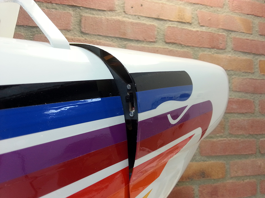
When the blind nut was out, the cause of all this became very clear. When installing the blind nut in the factory, the little barbs on the blind nut just folded inwards. This caused it to start turning, but this also made the blind nut going in in an angle, which was the reason my machine screw started binding in the first place.

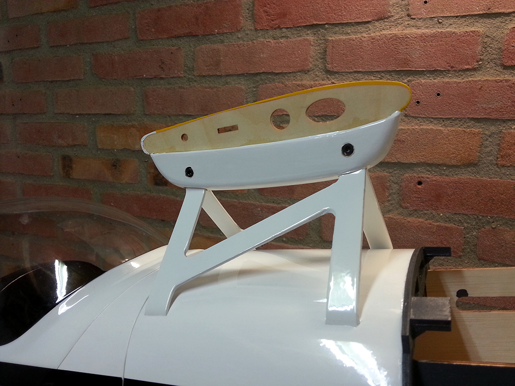
I couldn’t use the blind nut anymore, since the thread was stripped, so I temporarily installed the wing using a regular machine screw and a butterfly nut. I then fixed the hole in the fuselage with an all white decal cut to size. You can imagine I wasn’t too happy with this crappy blind nut installation job.

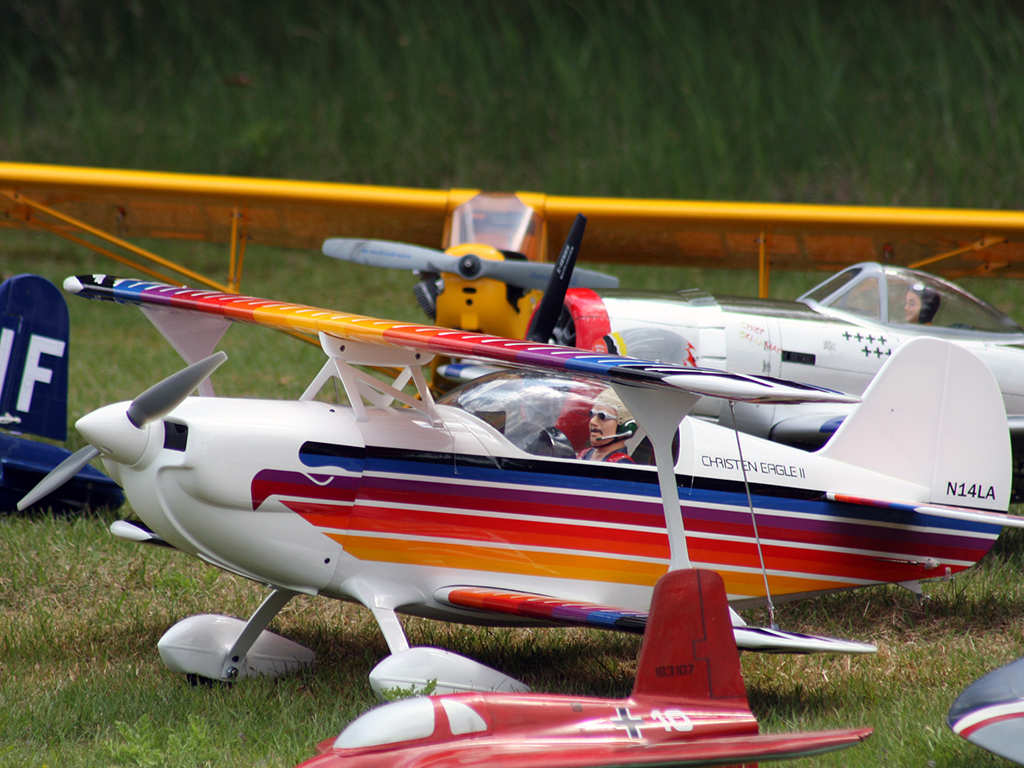
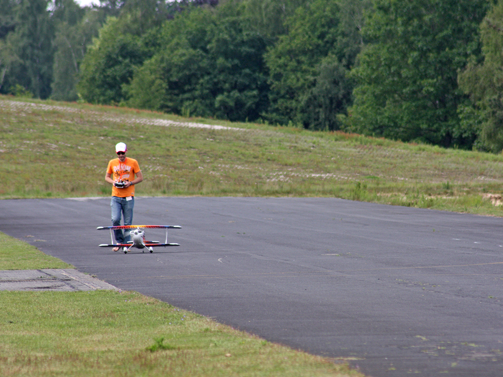
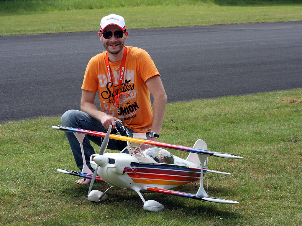
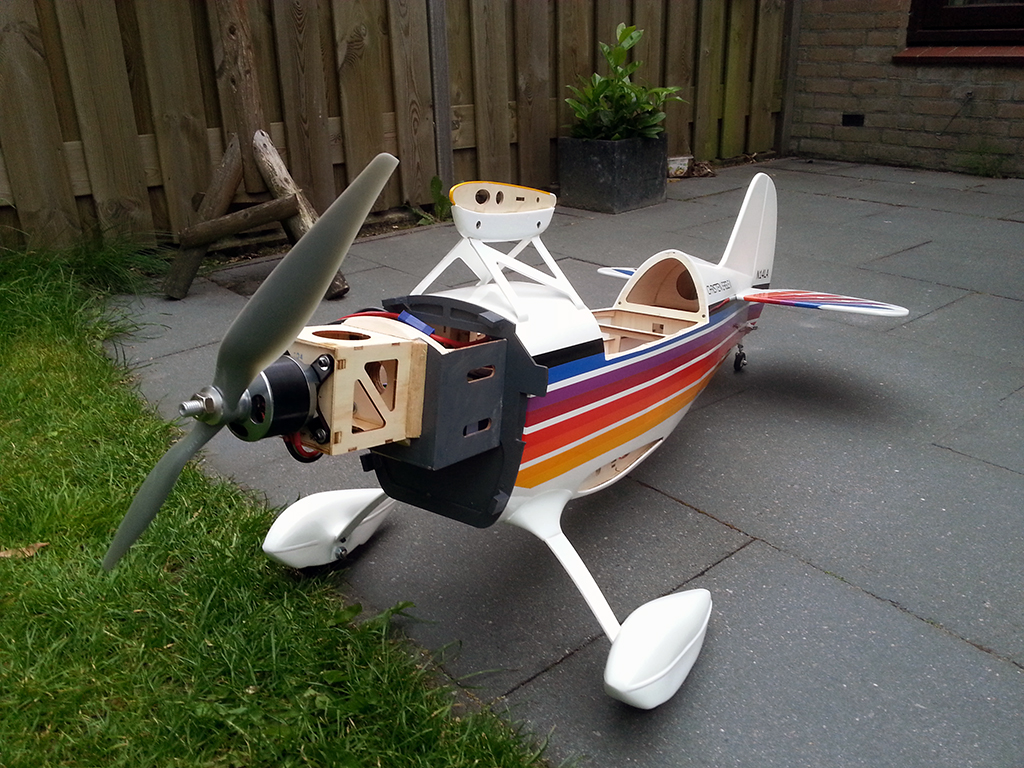
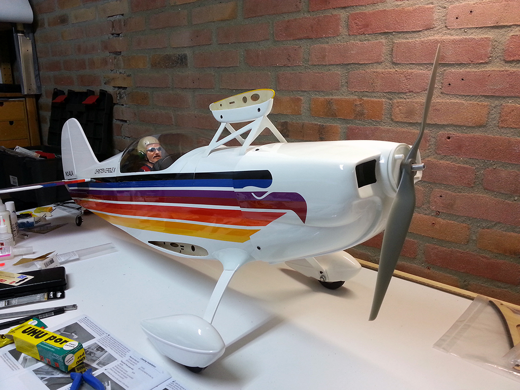
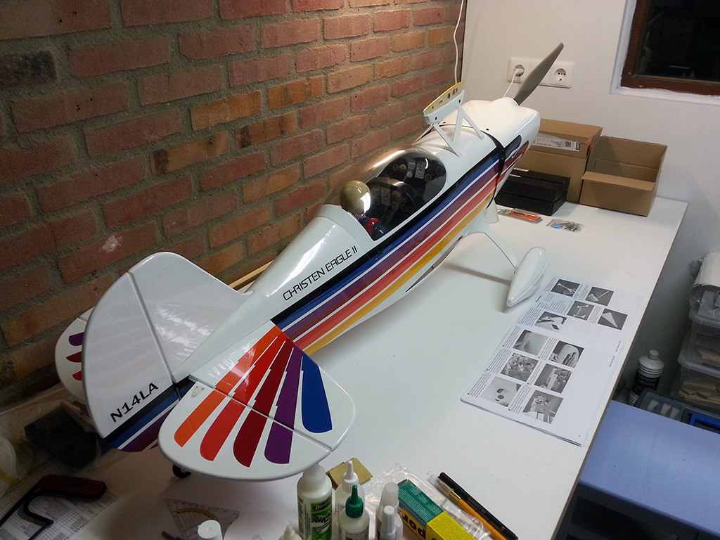
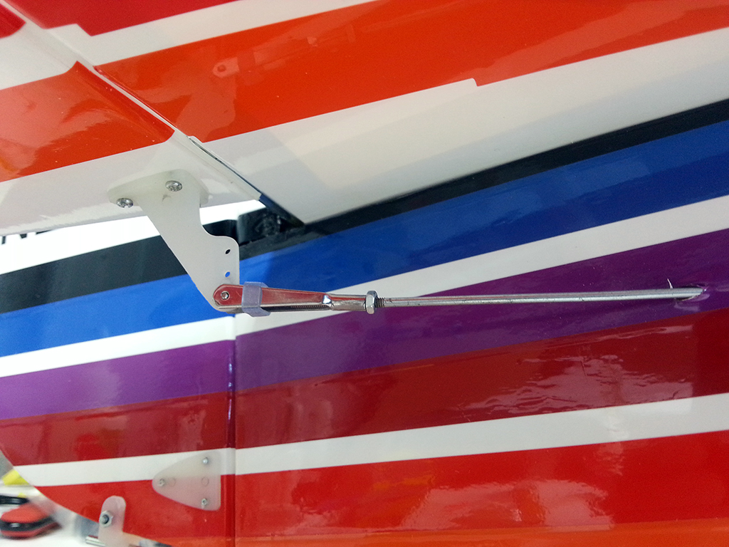
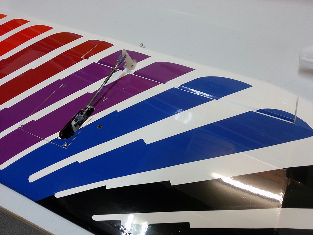
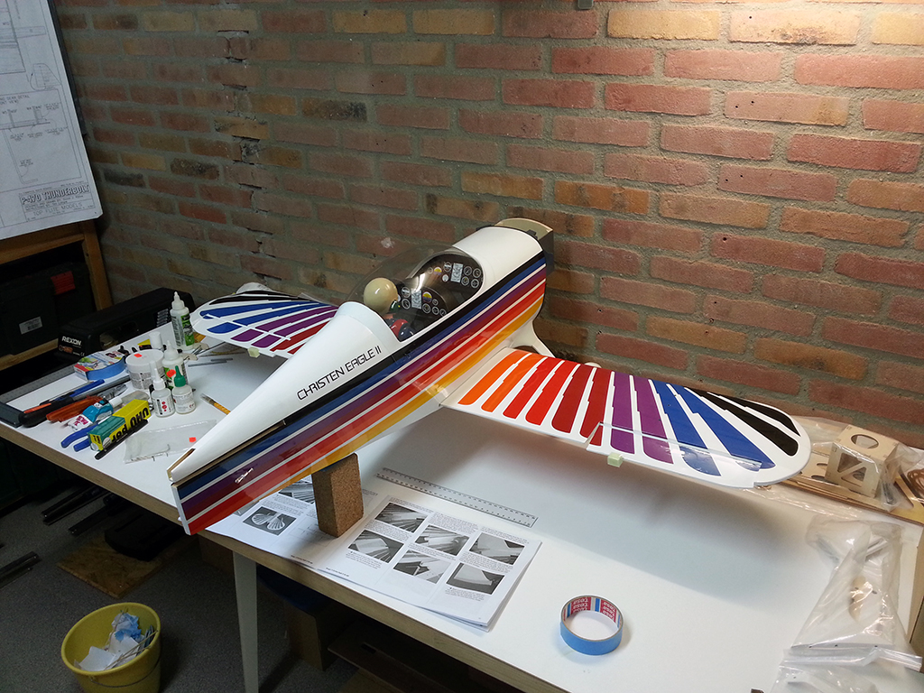
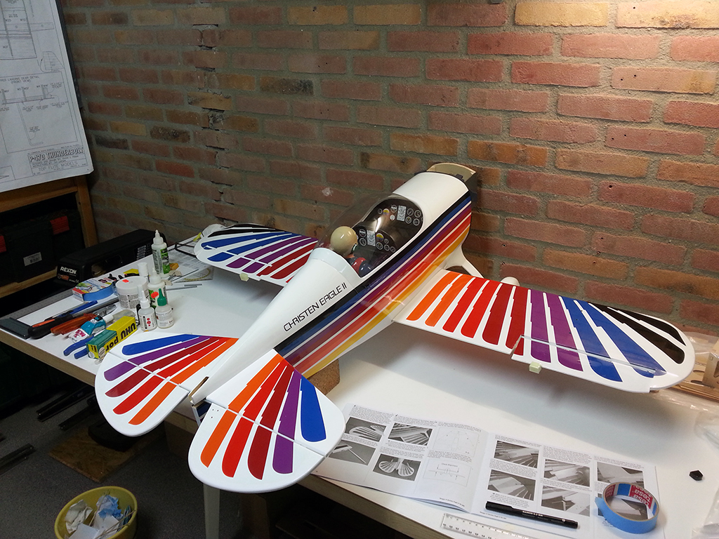
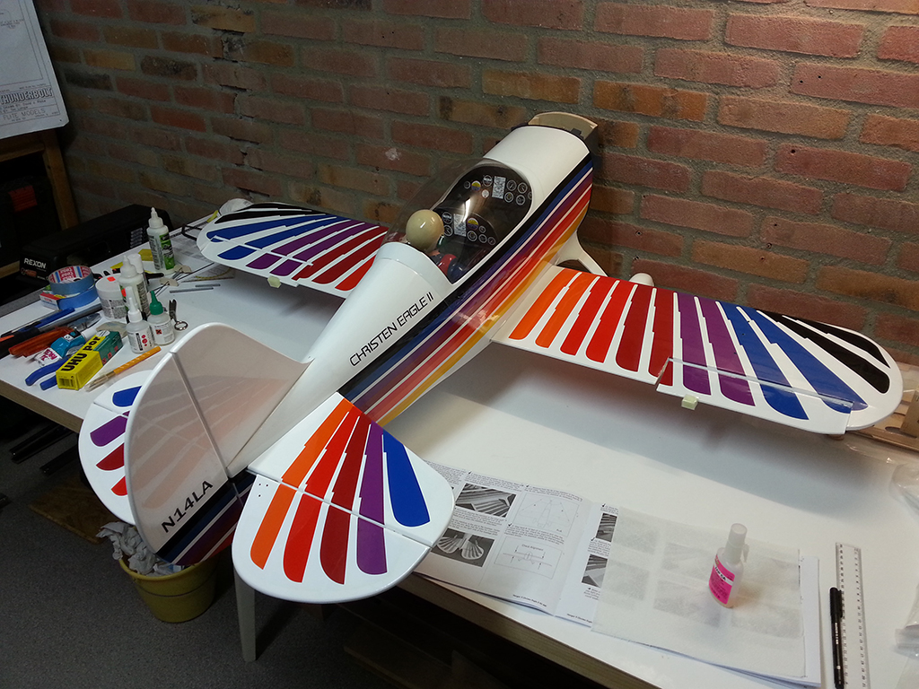
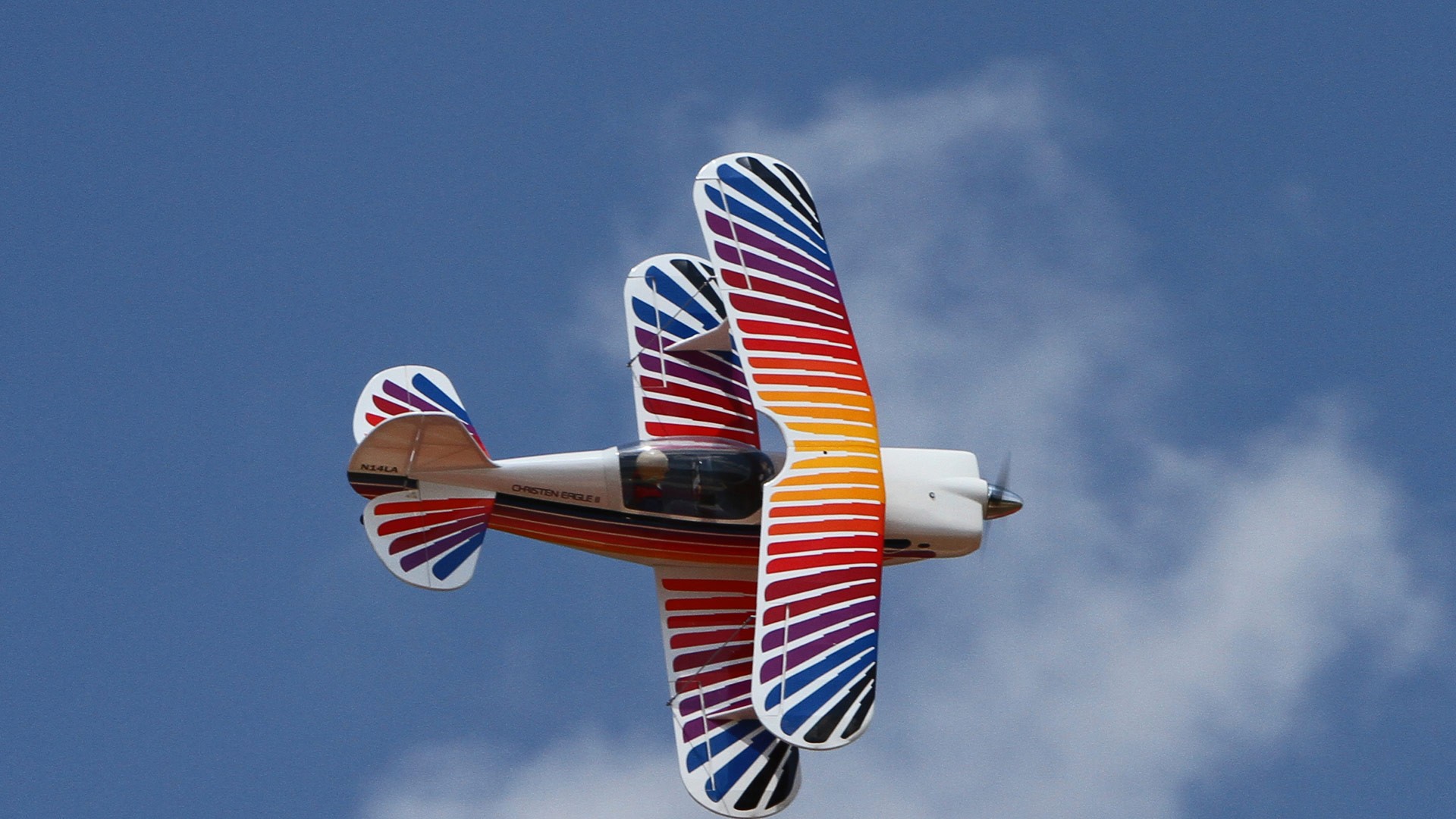
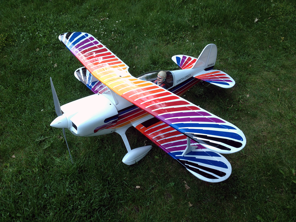
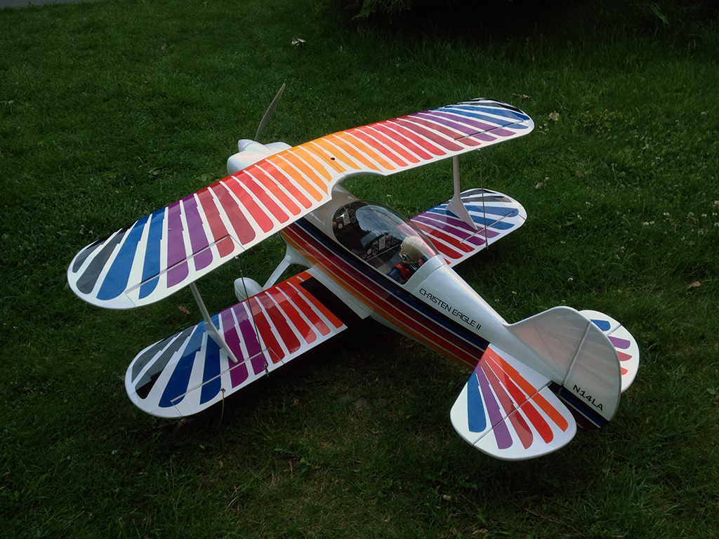
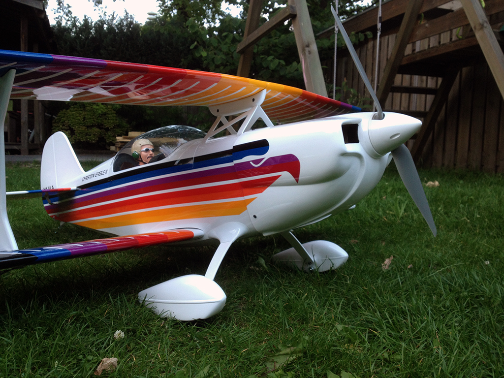
After having tackled this issue, everything went smooth again. The wings are on and I’ve assemblded the push rods inbetween the ailerons. And that was the last step of the building process in the manual. So today, only 18 days after I started ‘building’, I have finished my Christen Eagle II!

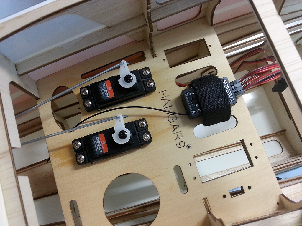
The CG was rather accurate straight away, but I will check again tomorrow and use some hook and loop tape to fix the batteries in the right place. The last thing left after that is checking and programming all control throws and maybe dialing in some expo.

Reamer to the rescue

In my last post I mentioned I found it very hard to drill a correctly centered hole in both prop and spinner, even with my drill press. Especially the spinner hole was clearly off center. I searched for reamers available online, but they all went up to a maximum of 9.5 mm, which isn’t enough. So yesterday I went to a local hobby shop and they offered great help. First of all, they had a good quality reamer with the steps 7, 8, 10 and 12 mm, starting at 1/4″, which is exactly the size of the stock hole in both prop and spinner:

I was surprised how easy it was to ream the prop hole with this tool (I bought a new prop as well). And I also bought this prop balancer you can hold between your fingers, works well, so I balanced the prop after reaming it, using a 400 grit sandpaper, finishing of with 1200 grit. Now I have a balanced prop that fits my prop shaft:

Lastly, it was time to ream and attach the spinner. I bought a new spinner too, since I blew up the supplied one, but I’m glad I did, because this one fits even better and seems to be of higher quality. Also, the prop fitted in the spinner without adjustments (you needed to cut out the holes in the spinner on the supplied prop). So I was very happy with this result, the visit to the LHS really paid off:

Alas, the spinner assembly vibrated way more than my clumsy drilled prop I tested the day before, so I guess the spinner needs balancing as well. I will do a test run with the prop only (didn’t have time for that anymore) and see if that’s okay. I hope I can get the spinner balanced as well though, as it looks very nice on this plane.

Power train

Last week I have mounted the Power 90 motor, which basically just screws on:

The speed controller required the use of tie wraps, as it does not have any mounting brackets, which is a pity. Anyhow, this works as well I guess but I’m a little afraid the wraps might wear the housing of the ESC. Then, there’s the on / off switch for the controller. A nice feature that’s not present on most speed controllers I know of. However, the prepared opening for a switch (behind the covering, used for the gas or glow option) was positioned too far from the controller and it also was too large. For a moment I thought about cutting a hole in the fuselage, using the black covering to hide the switch, but then I saw these tabs for the cowling: bingo! Easy to mount, easy to operate and it doesn’t show in flight. The final ESC installation:

Then I drilled out the prop hole to 10 mm with my drill press (the precision hole was 9.5 mm and the center section 1/4″). I drilled from the front with a high quality metal bit and with a bit of filing I think I got the best possible result using this technique. Using a reamer wasn’t an option, as the reamers I found only go up to 9.5 mm. I am still in doubt whether to use this prop or not, but decided to do a test run to validate my result (before balancing). Here’s the Christen after its first test run of the power train:

The motor and motor box do not vibrate at all, so that is a good sign. I did a few low throttle tests and eventually powered it up to almost full throttle. I was astounded by the power of this setup! Wow!

Drilling the spinner didn’t work out very well by the way. It’s off center by only 0.2 mm, but it makes the motor vibrate even on low throttle. This is my biggest challenge on the whole build… maybe I can find a spinner with a 10 mm prop hub hole (aluminum?), but it’s hard to find one, especially since most sites and resources do not include this figure in their specs. So for the moment I can only run without the spinner.

While fitting the cowl, the ESC switch proves to be perfectly hidden, great spot for this little handy fellow:

And with the cowling fitted, the fuselage is finished!

Various hardware

Time for some more Christen Eagle building. I need to get this bird flying ASAP so let’s continue!

This is the battery tray with two 4s 4000mAh batteries. The Turnigy straps are of good quality, way more firm than regular hook and loop straps:

Installing the clevises to the control horns (and to the servo’s):

The fuselage is very, very roomy. For the electric version I’ve chosen, this section only contains two (digital) servos and a receiver:

Then I went on to the ailerons. Not pictured, but since it’s a biplane you need to hinge four ailerons, having three hinges each. The hinging itself was uneventful, but I came across three more issues during this part of the build.

First of all, the ailerons contain little tabs to connect them together (each pair of wings only has one aileron servo) and they protected the other wings in the shipping box from these tabs with little squares of foam rubber. That’s cool. But what’s not cool, is that Hangar 9 used a lot of high tack transparent tape to hold this protection in place. It took quite some time to remove the tape and I accidentally teared off some decorative covering (which was glued back later on). But after removing, I still needed to use strong chemicals to remove the remaining glue of the tape. I think, since this isn’t a structural functioning part of the plane itself, they should’ve used small parts of low tack tape. Apart from the tape, I found all ailerons to be curved a little, making it impossible to align them perfectly in the center of the aileron bay. The last issue I found while installing the ailerons was that the push rods from the aileron servos to the control horns actually hit the wing on full deflection. I recut the openings in the servo cover of the bottom wings and now everything is okay.

This is how the final aileron assembly looks:

Next came the installation of the cabane struts for the upper wing. Looked easy, but it turned out one of the blind nuts inside the fuselage wasn’t positioned correctly. Since there’s no flex in the metal of the struts, it took some TLC to get them in place:

For the electric power option I chose, a motor box needs to be mounted to the firewall, using four blind bolts with socket head screws and triangle stock glued on with epoxy. A plywood drilling template is supplied and the motor box is completely preassembled. Couldn’t be any easier:

Next up is the motor and ESC installation, so I’ll have to get the soldering iron out. After that only the cowl and upper wings (together with the wing struts) have to be fitted.

Tail and legs

About a month and a half ago, I received the first parts of my new ARF: the Christen Eagle from Hangar 9. I immediately started fixing the cockpit, as you can see in my previous post, but waited with any further assembly tasks until all parts were in. Two weeks ago I received the Power 90 motor which was on backorder and on the 6th of May I finally started building. I also do have a deadline… I want to fly this plane at our annual fly-in at the club which will be held on May 31 this year.

I will not post any detailed construction descriptions or pictures, as that would only replicate the manual (building an ARF isn’t a unique process so to say), but it’s nice to share some building steps here.

Per manual I started with the main landing gear. You need to bolt a few parts together, but the most work goes to the fairings (which need to be cut in shape) and the wheel pants. After some drilling, epoxying plywood doublers and a lot of small adjustments and alignment fine-tuning, the Eagle stood on its’ own feet:

To prepare for installing the tail section, the lower wings were temporarily installed:

As you can see, I am finished with restoring the cockpit as well. The front dash is in and the pilot is secured with some screws as well, next to the epoxy I used earlier:

Then, you need to hinge the elevators and install the stabilizer. It was hard to get the alignment correct, because the main legs weren’t exactly symmetrical. The body is leaning to the left slightly and it’s almost impossible to bend those sturdy legs. I’m satisfied with the result though, and after cutting away the covering in the center section, the stabilizer was glued on with epoxy as well:

Same goes for the fin and rudder. Hinge, align, remove covering and glue in place, using a square and hoping for the best :)

Lastly, I’ve installed the tail wheel. A very straight forward job:

I think it cost me four to five evenings to get to this point. I didn’t came across any major issues, besides the fact that the fairings for the main gear are brittle (they easily crack, could be an issue when landing roughly) and that they are a little hard to get to the right shape exactly, being flexible and all. I used Uhu Por for these fairings by the way, instead of the silicon glue suggested. Works fine.

Another ‘project’

While I’m still building the Thunderbolt, I figured I need a new challenge in terms of flying and I would also like to fly a bigger plane than the ones I own right now. Due to being busy in other areas, the Thunderbolt may take a while to get finished, so I decided to buy an ARF for the upcoming flying season. In addition to my under construction warbird, I opted for an aerobatic civilian plane: the Hangar 9 Christen Eagle II 90. Power will be electric.

Yesterday most of the parts arrived. I now have the airframe, prop (APC 17x8E), ESC (Hacker MasterSPIN 80), batteries (2 sets of 2x 4S 4000 mAh 35C Turnigy nano-tech packs), receiver (Graupner HOTT GR-12) and all battery connectors. The motor (e-Flite Power 90) is in backorder and will join the party in a few weeks. I still need to pick the servos, but they ought to be digital and high-torque.

Upon opening the box of the plane I was in for my first surprise. Not only had the pilot become loose, it also smashed both dashboards. It is a common issue with this kit, that the pilot tends to come loose, because oddly enough, Horizon glues the pilot onto the covering inside the cockpit with only a few drops of glue, instead of gluing it to the wood underneath the Oracover. So I was prepared to secure the pilot from beneath with some screws, but it turned out to be a little worse than expected:

  • The pilot came loose, and..
  • … tore off some covering,
  • … knocked out the middle dash,
  • … slammed into and completely punctured the front dash,
  • … made lots of scratches on the inside of the canopy with the paint of his helmet.

And since the canopy is glued on already, everything inside the cockpit is hard to reach, let alone glue or fix. But tonight I took a shot at it and enjoyed myself as if I was building a ship in a bottle, working only through some small holes on the sides. I patiently removed all scratched with a damp cloth on a small stick, removed the covering under the pilot as well as the little snips around the base of the pilot, painted all bare wood black to cover up the missing covering and removed some glue patches on the inside of the canopy while I was at it. I then glued the pilot back in place with some 30-minute epoxy and also found a way to re-attach the middle dash: I put some drops of contact glue in the corners of the dash and on the corners of the intended location, shifted the dash to the right spot on two skewers acting like some rails and, when the contact glue cured for about ten minutes, removed the screwers and pressed the dash into position. Everything worked out great. Tomorrow I will glue in the front dash with white glue and I will also secure the pilot with some screws from beneath.

As you can see, we’re almost good to go again and if I am ready with the cockpit I will clear out some space in the workshop and start following the supplied instructions.