Fuselage assembly preparation

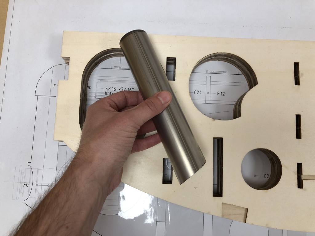
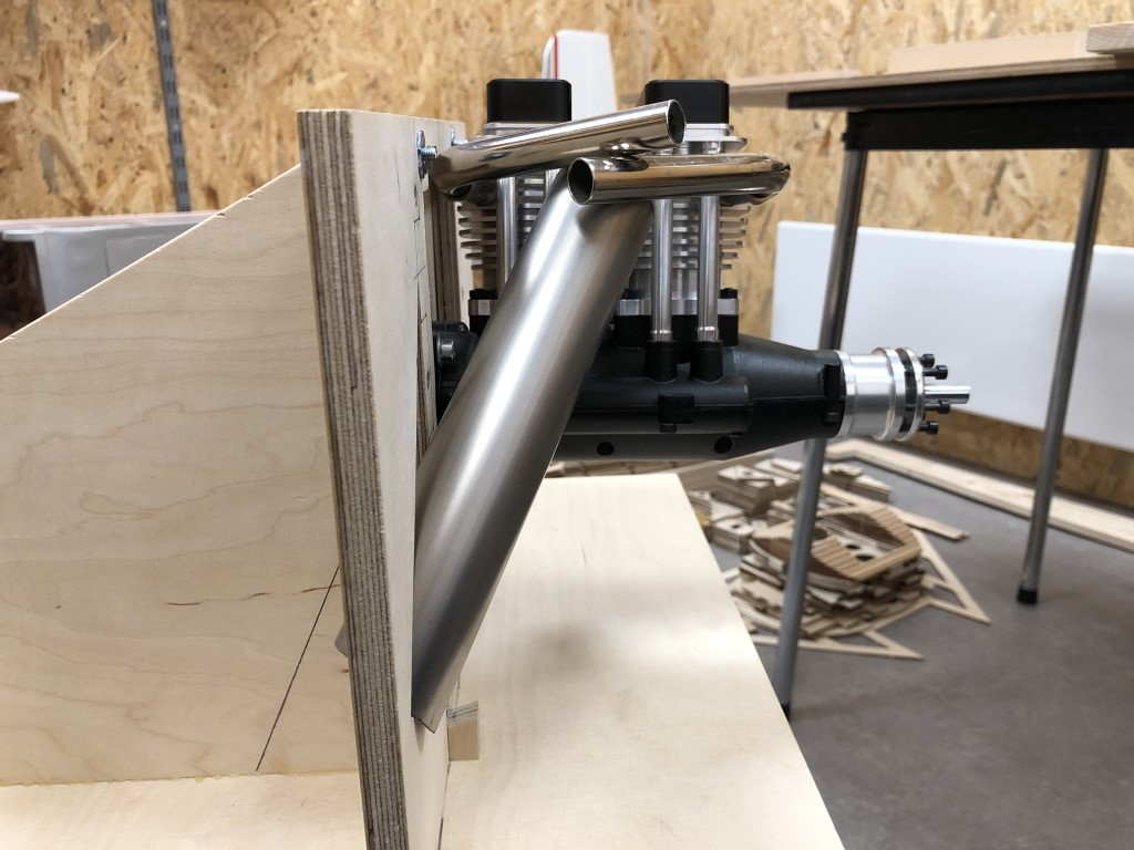
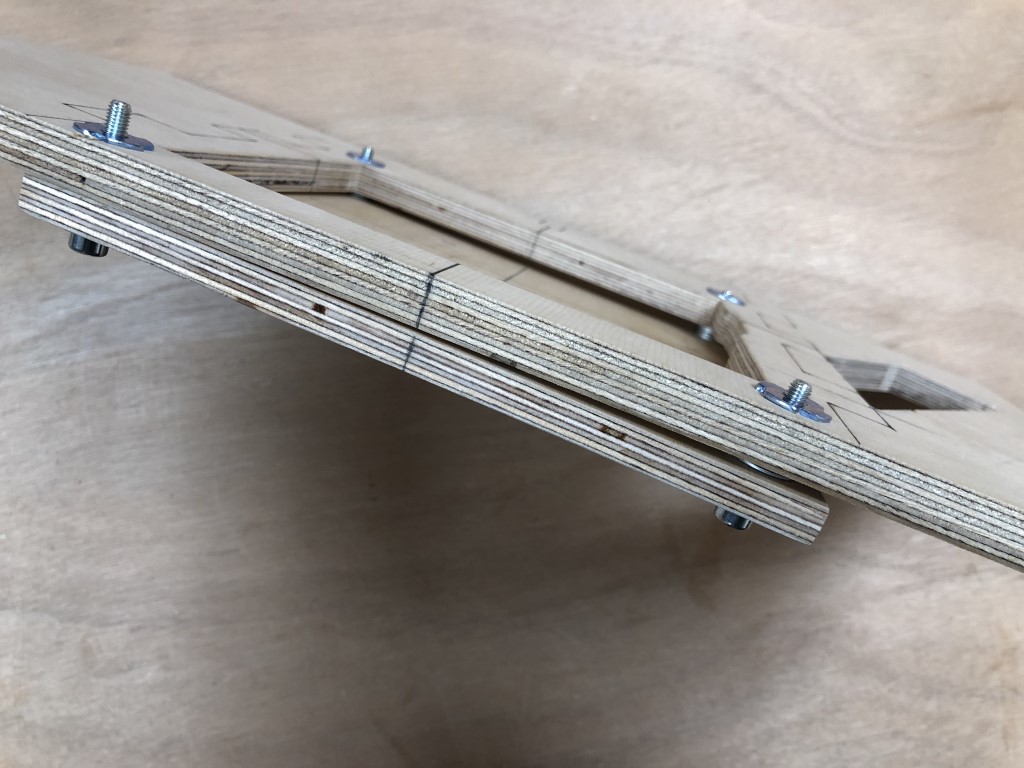
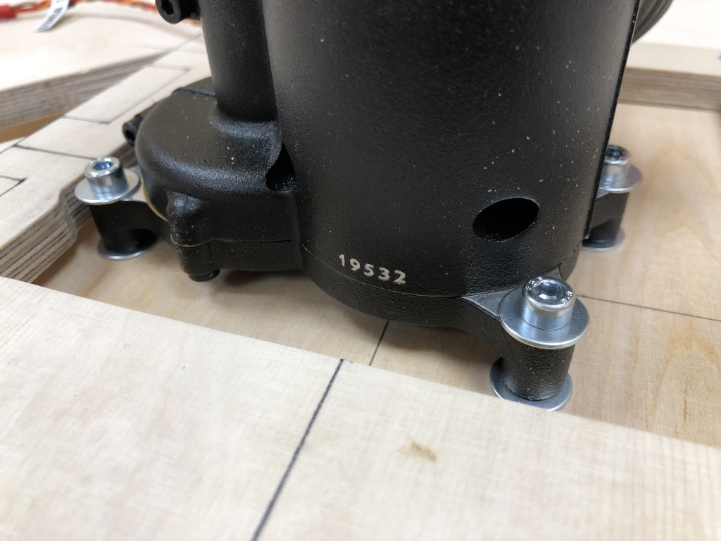
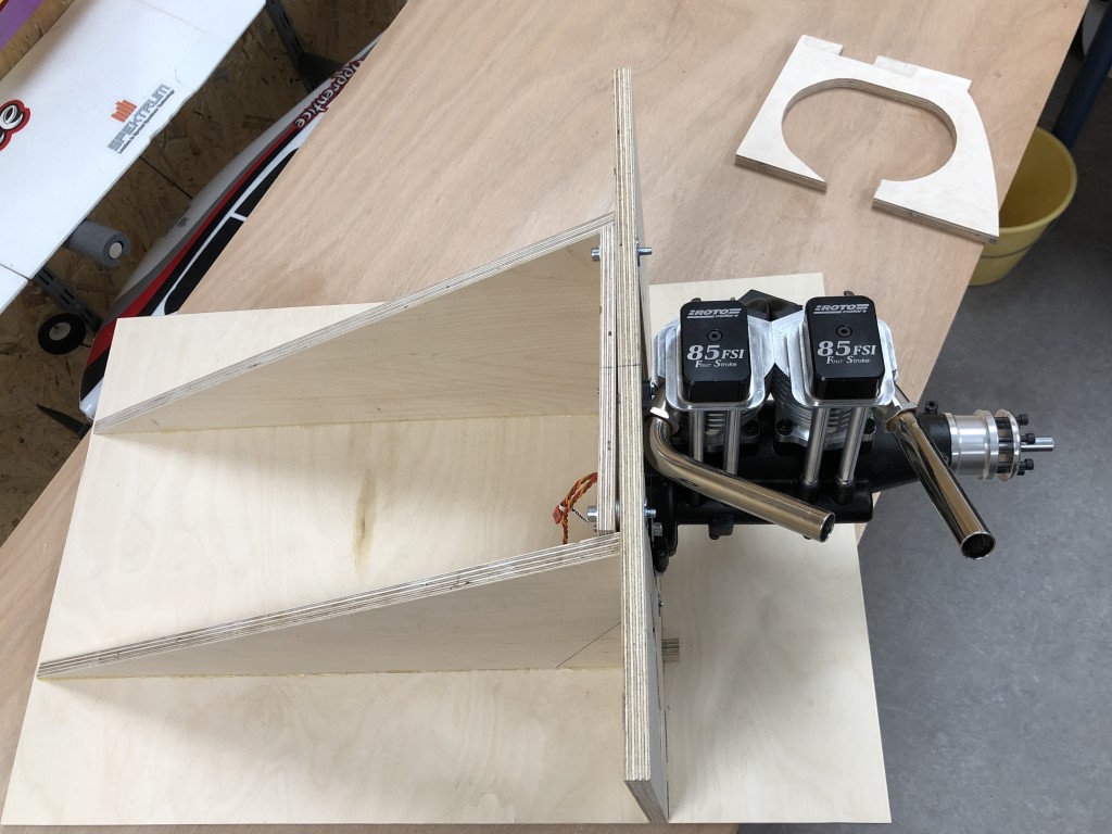
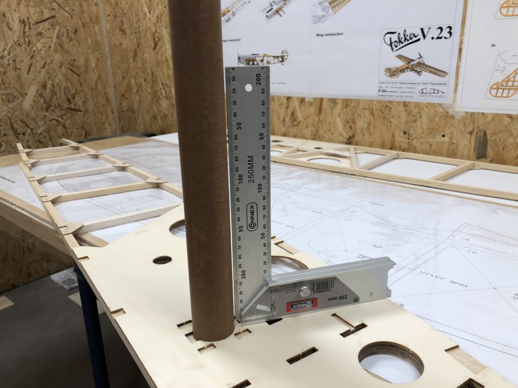
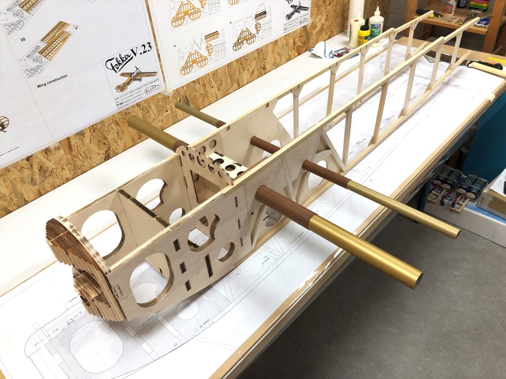
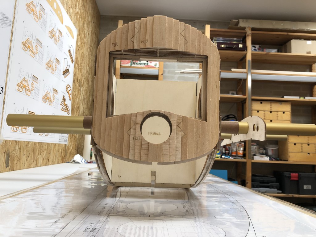
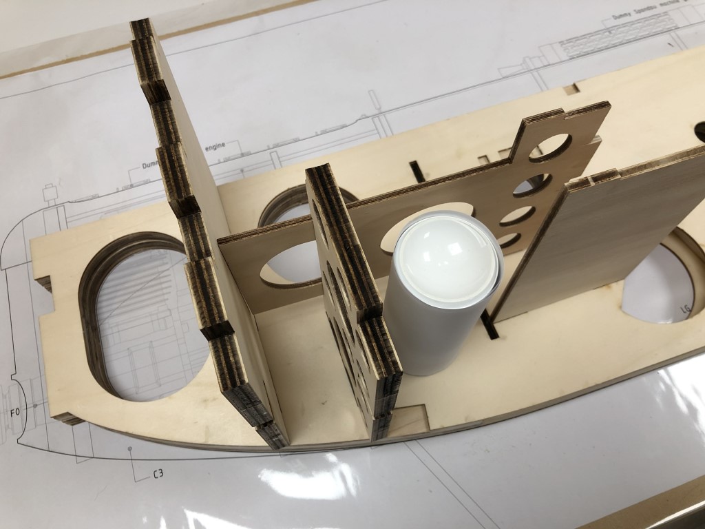
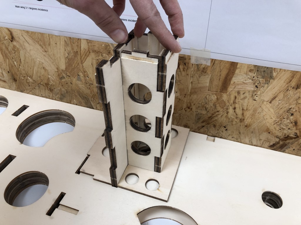
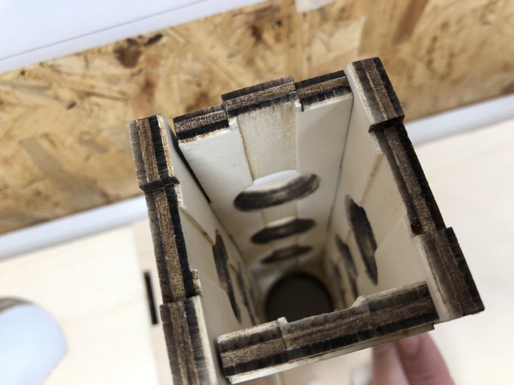
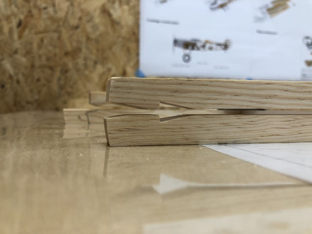
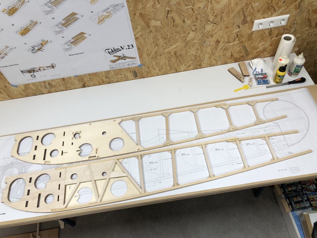
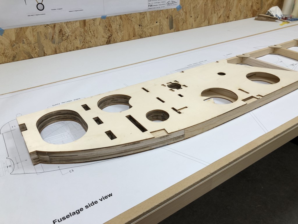
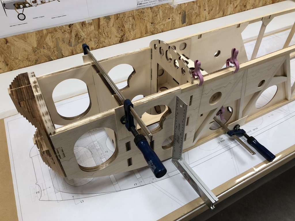
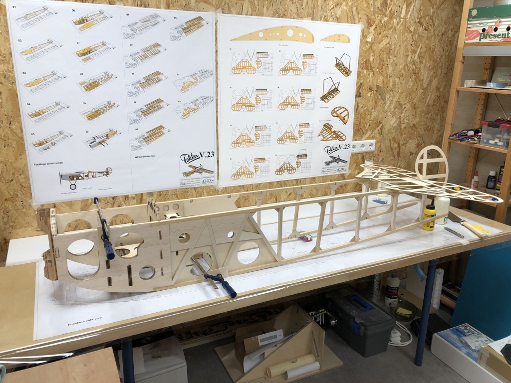
I don’t want to assemble and glue the fuselage before I’m absolutely 100% sure about the firewall and the attachment of the landing gear struts. To prepare for this step I did an alignment test, and it seems that I can get it nice and straight with only a couple of extra clamps:

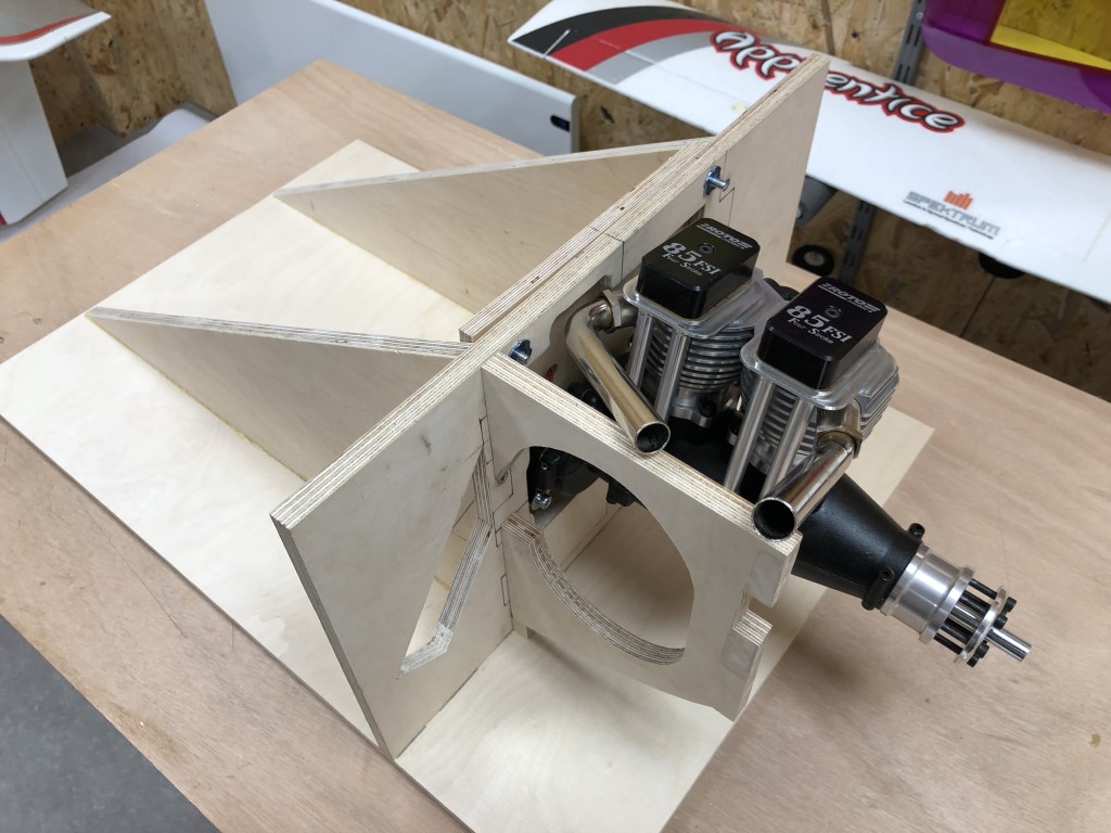
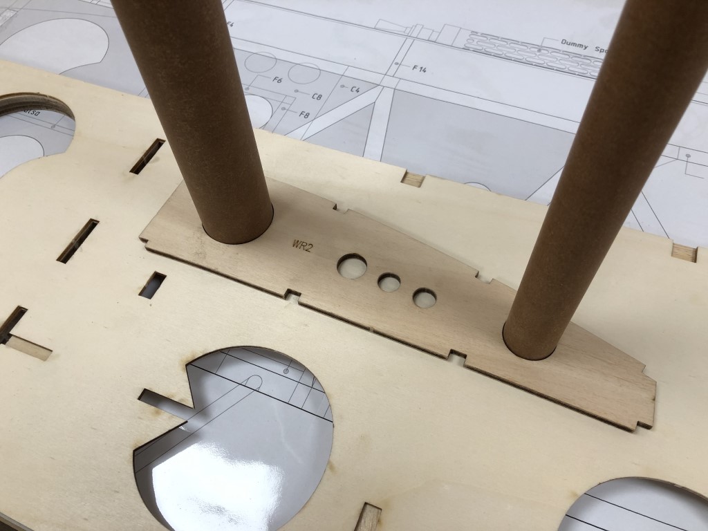
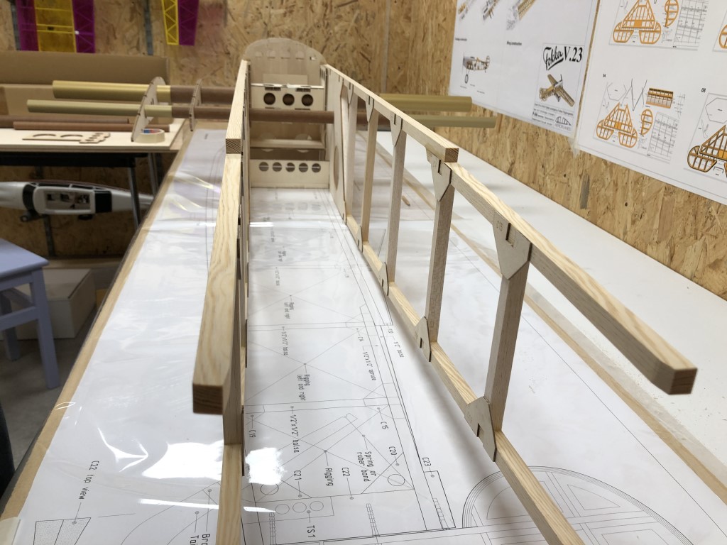
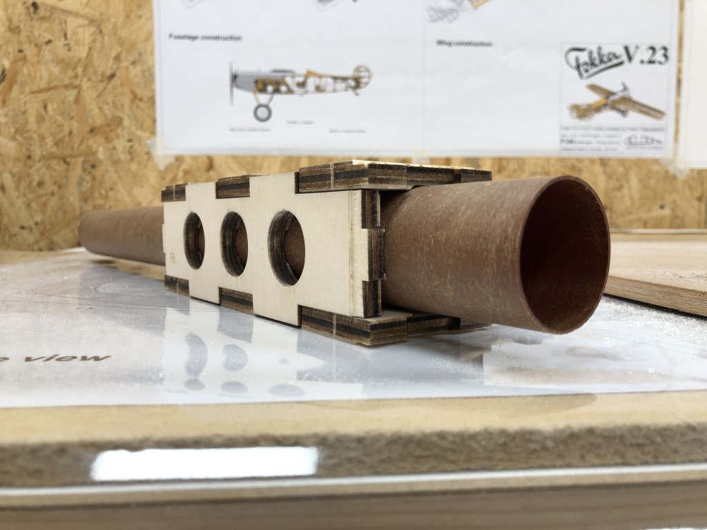
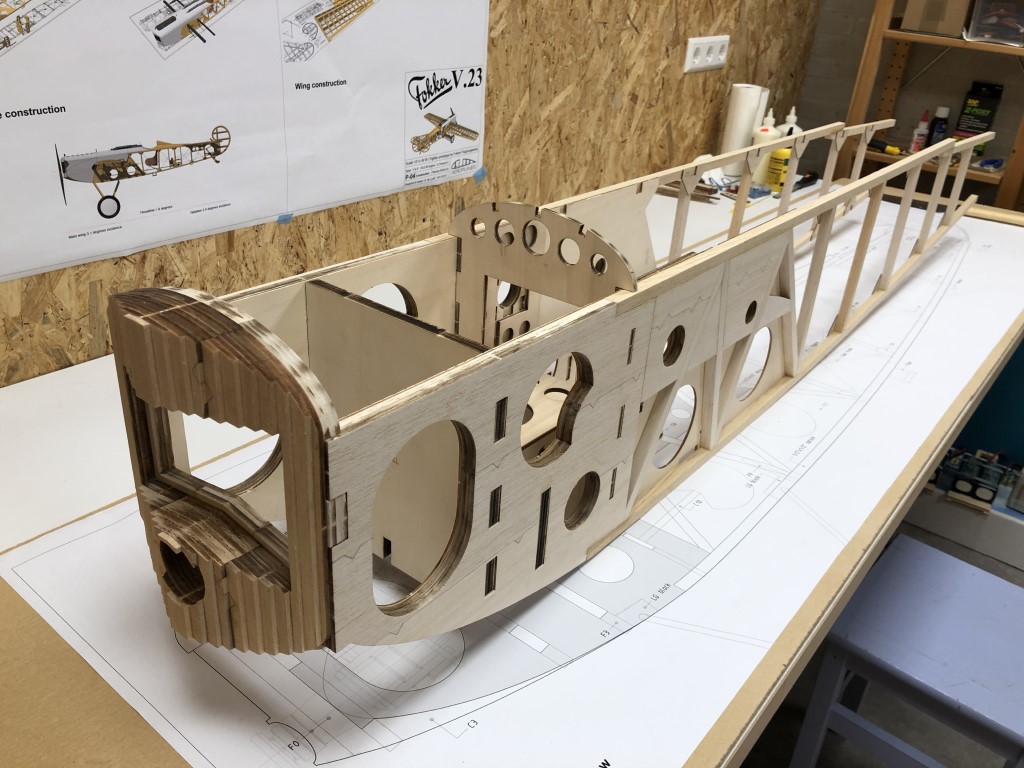
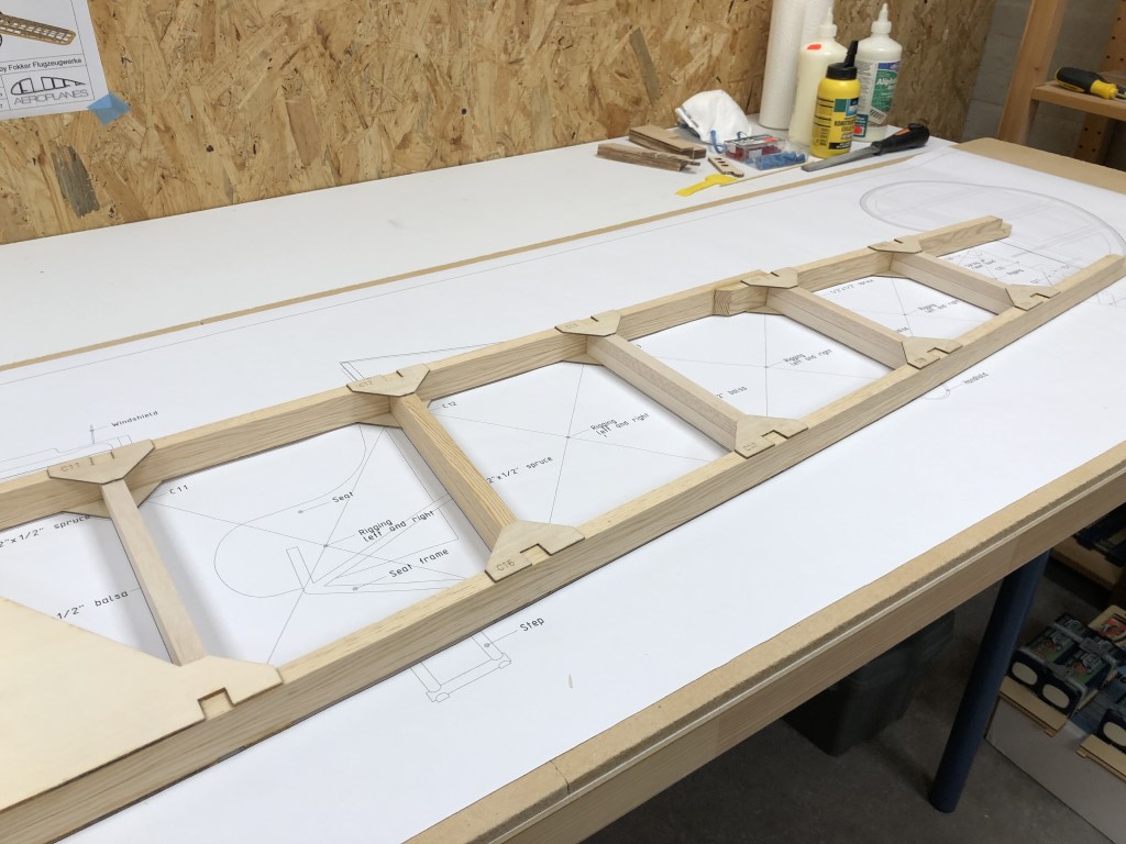
Couldn’t resist putting the tail pieces on there as well. Looks very good, nice and straight. I will do another test including the wing tubes before final assembly, making sure they are perfectly parallel and horizontal. Thinking about using 24h epoxy so I have the time to clamp and align everything without having to rush while the glue sets. If I would use white glue, gluing part by part, I probably would build up quite a deviation over that long fuse, giving me no options to do some final fine-tuning and alignment.

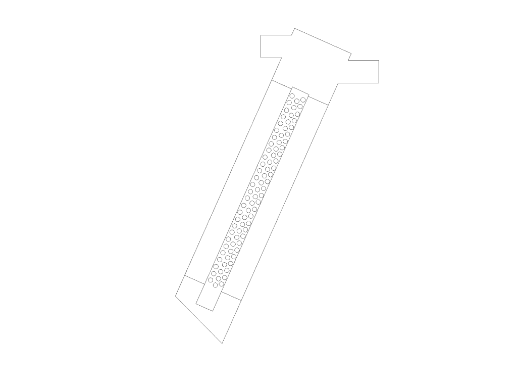
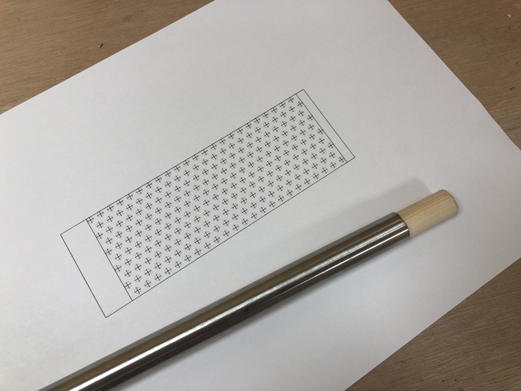
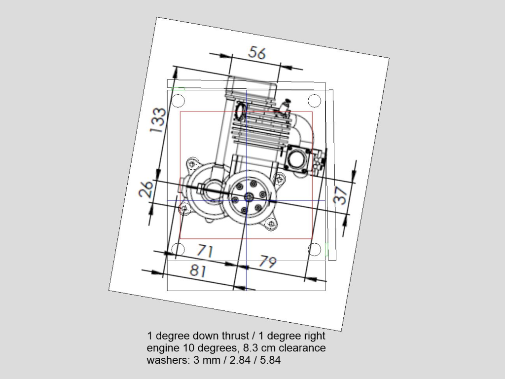
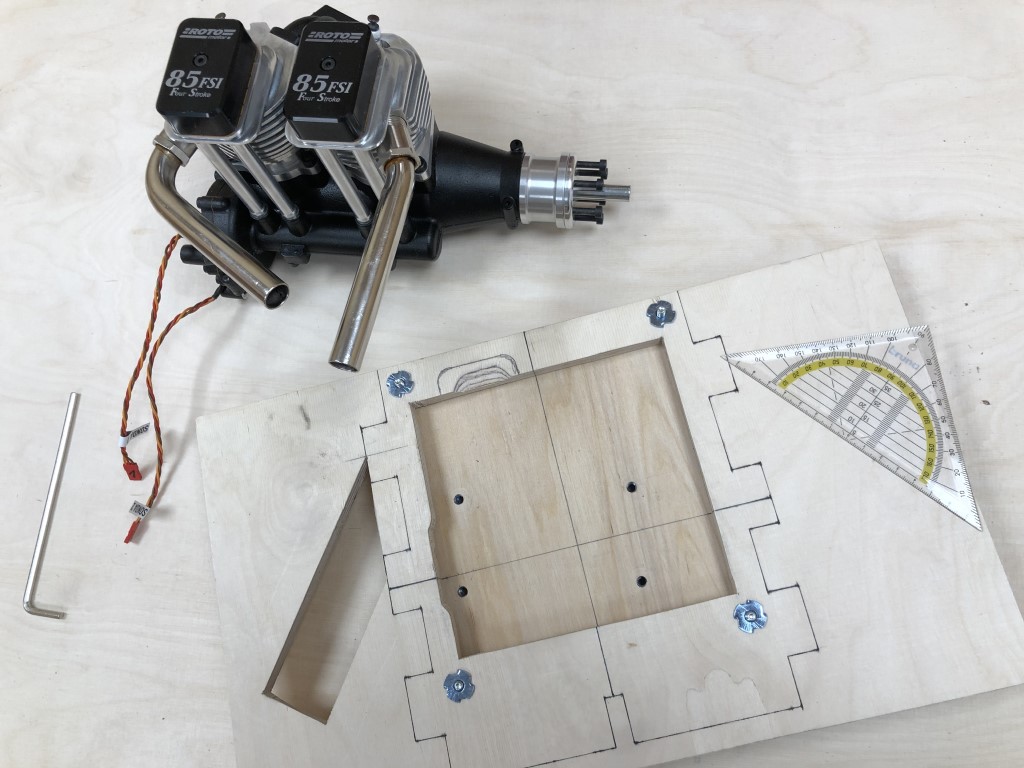
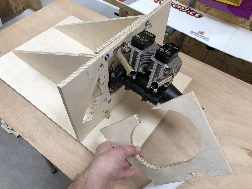
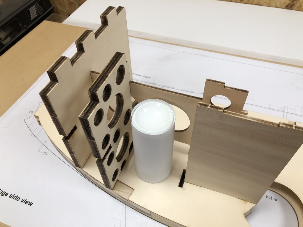
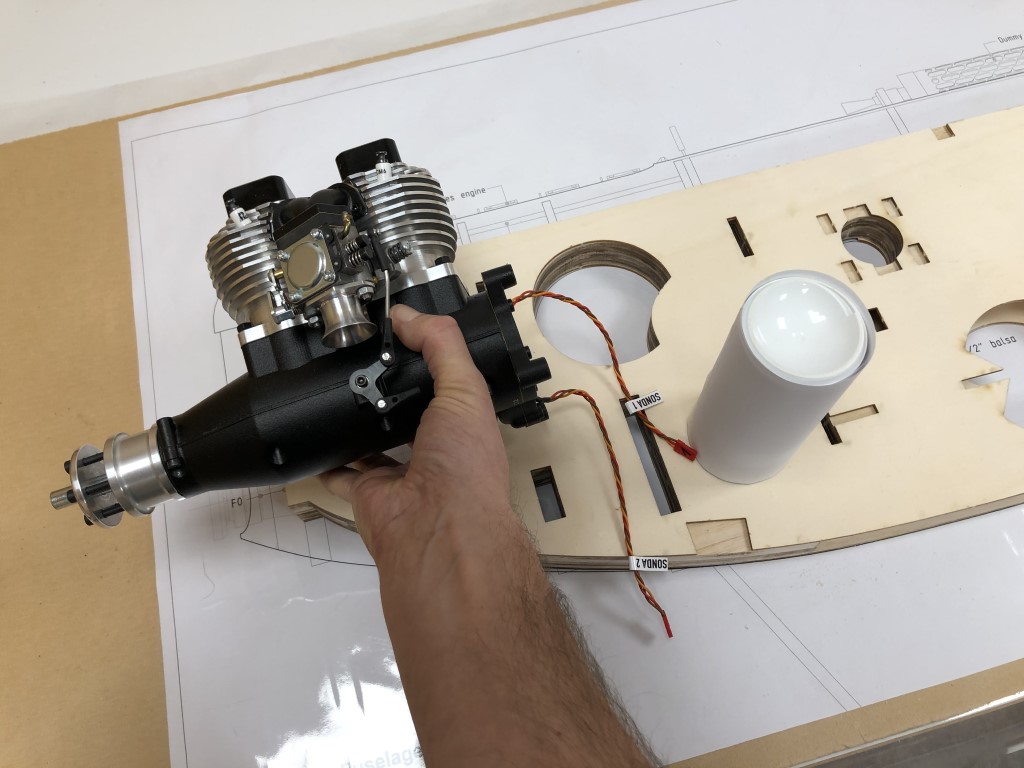
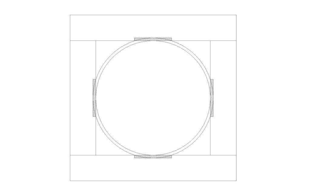
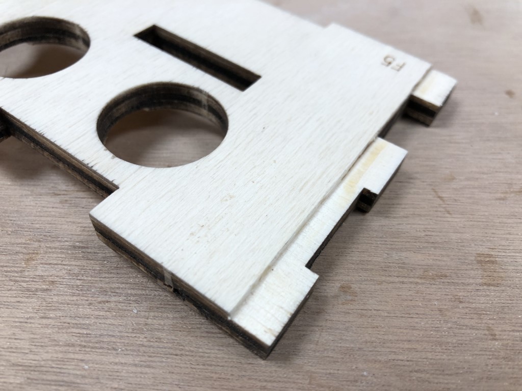
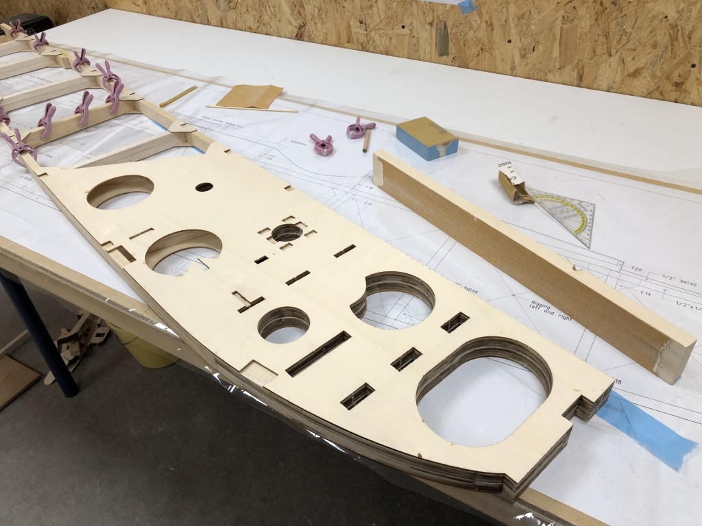
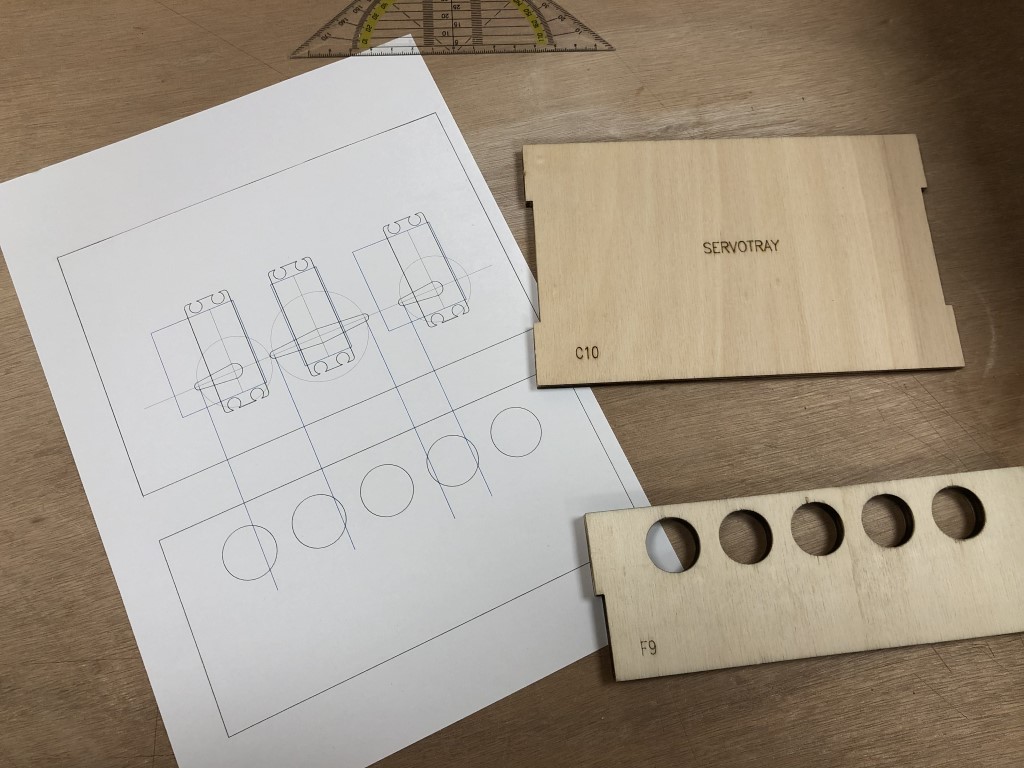
Before I can assemble the fuselage, I also need to finish the servo tray. Easier now it’s not in yet. I want to place one rudder servo and two elevator servos in here. And I want to leave options open, so I can decide whether to run them on one channel with a split cable, or run them on a separate channel each. The latter is way nicer, but I’d need a new radio. Also, this way I can still decide to orientate them pointing either inward or outward, depending on what gives the nicest geometry for the push-rods. So, I drew a template in CAD:

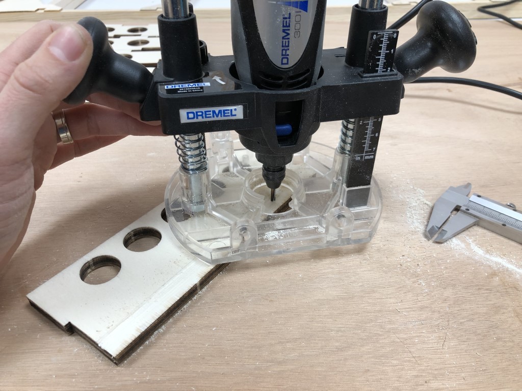
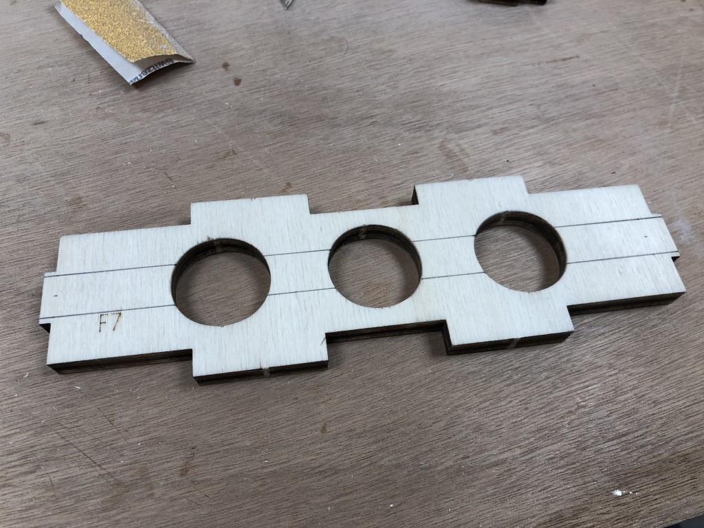
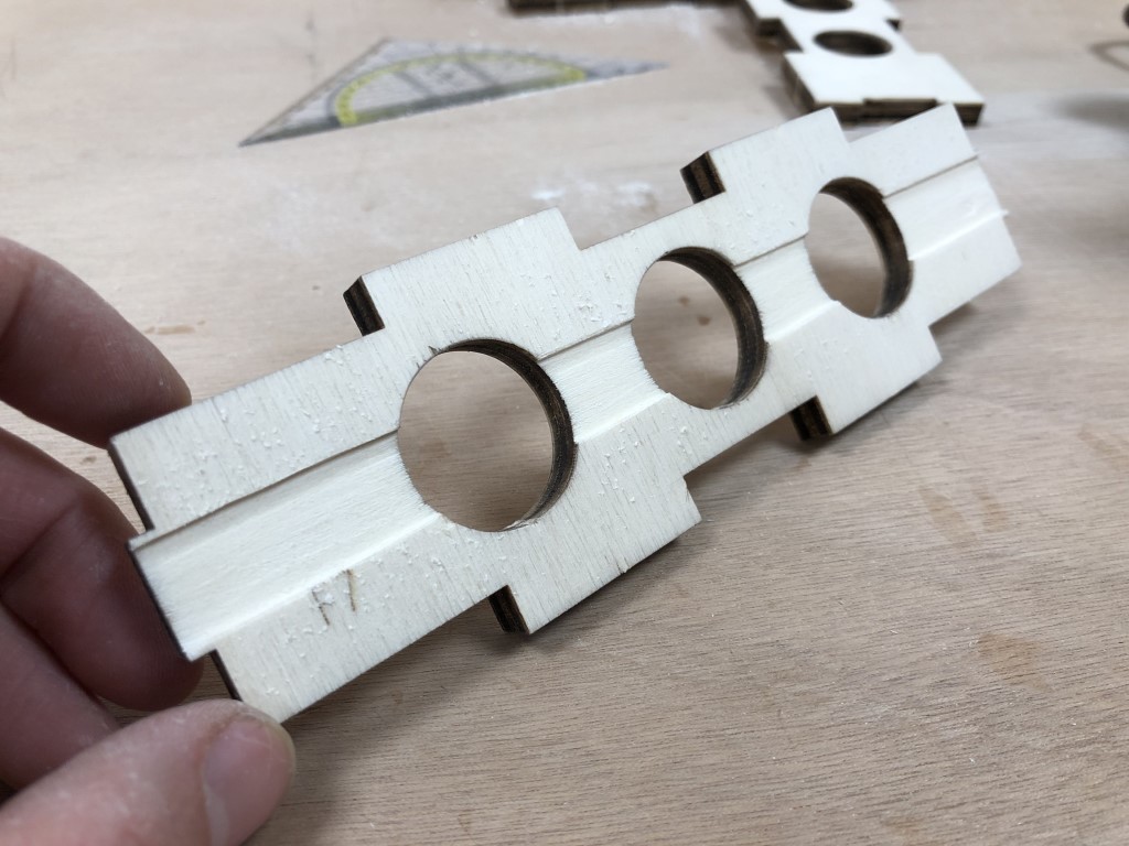
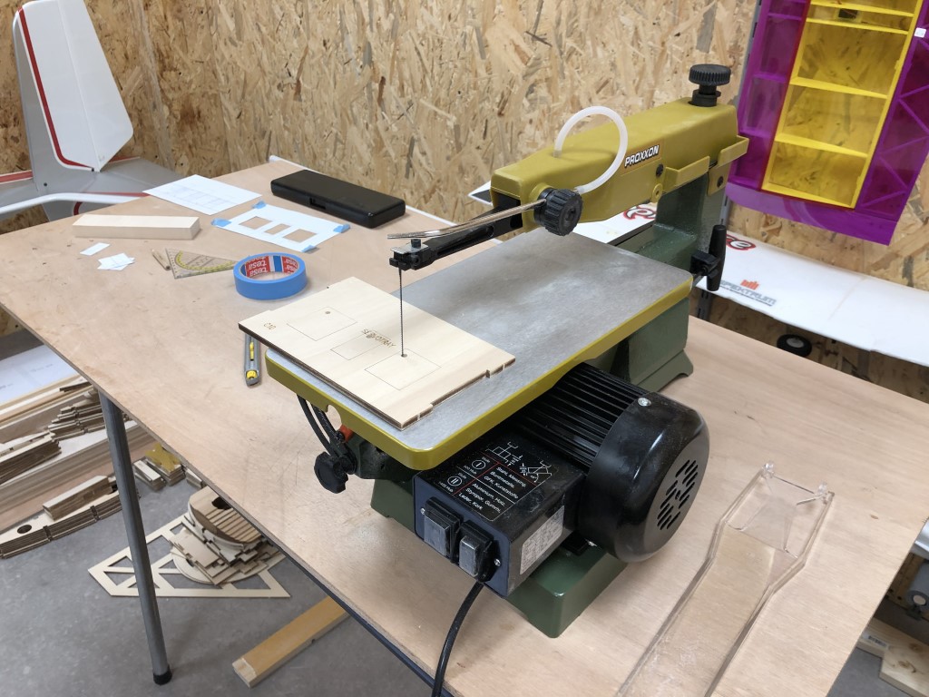
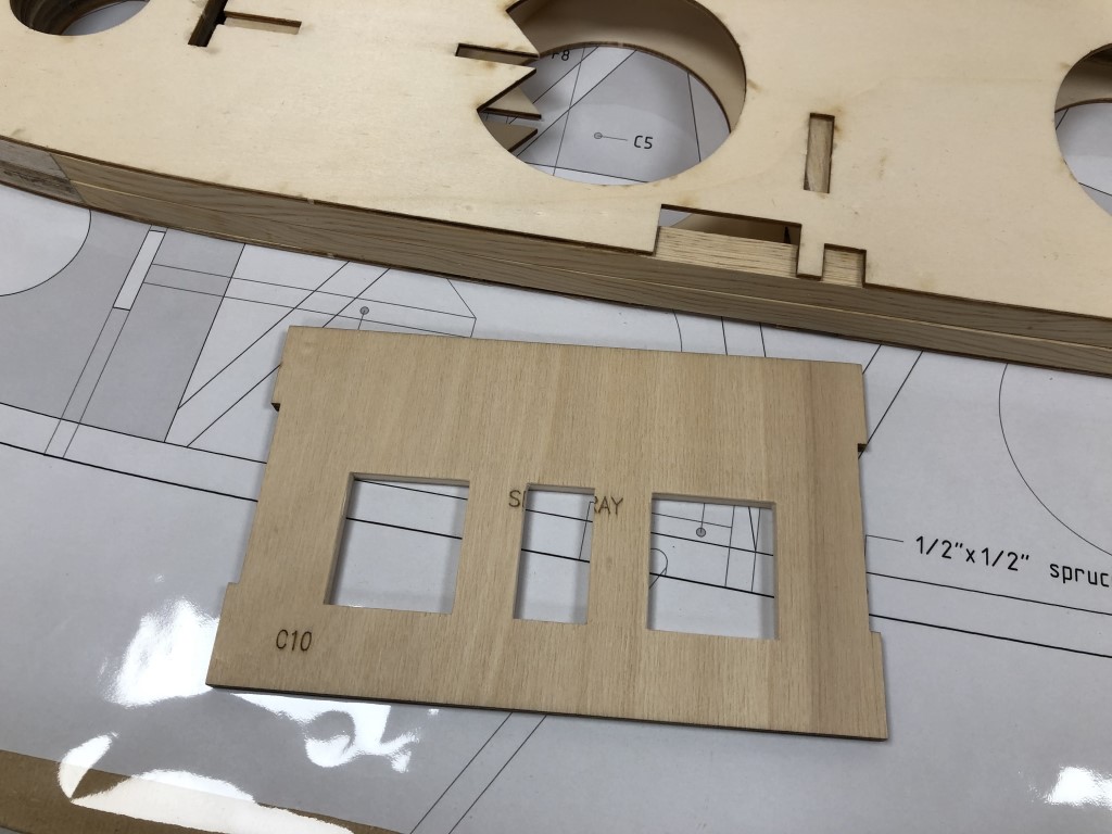
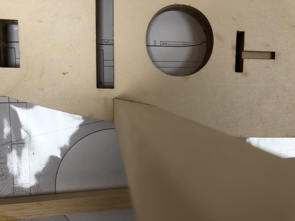
And cut the holes in the tray nice and straight:

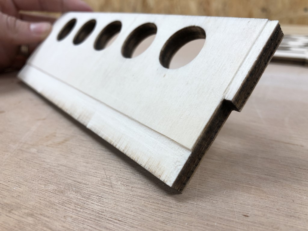
Another small job finished:

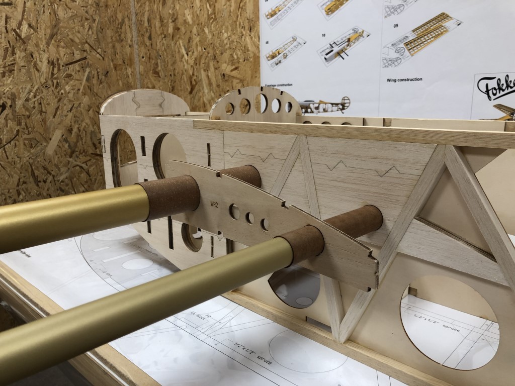
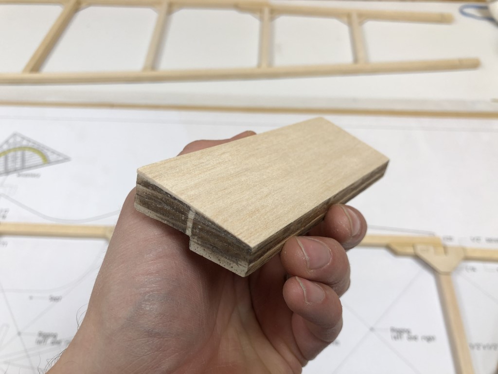
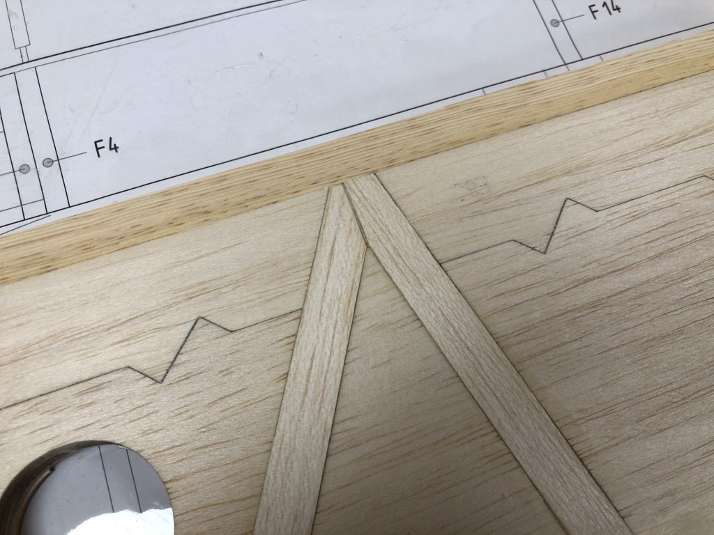
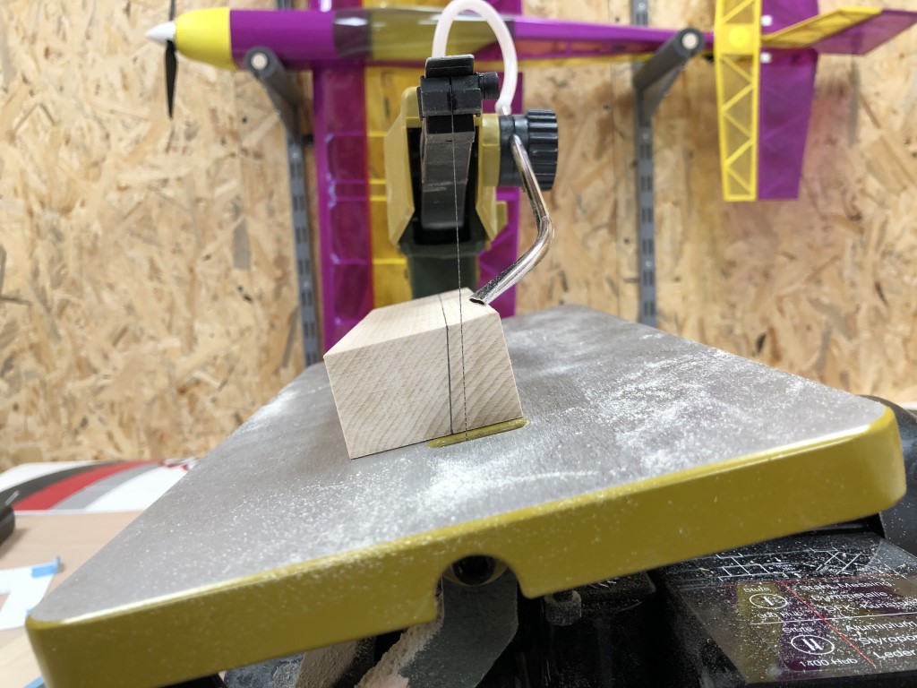
Then onto the landing gear blocks. The plans suggest using basswood, but the stock LG blocks are not big enough, so I decided to cut them myself from a larger block of basswood. One of the sides is angled, which can be cut with the scroll saw perfectly well, if you’re patient:

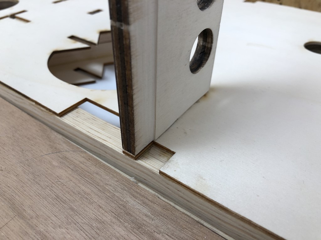
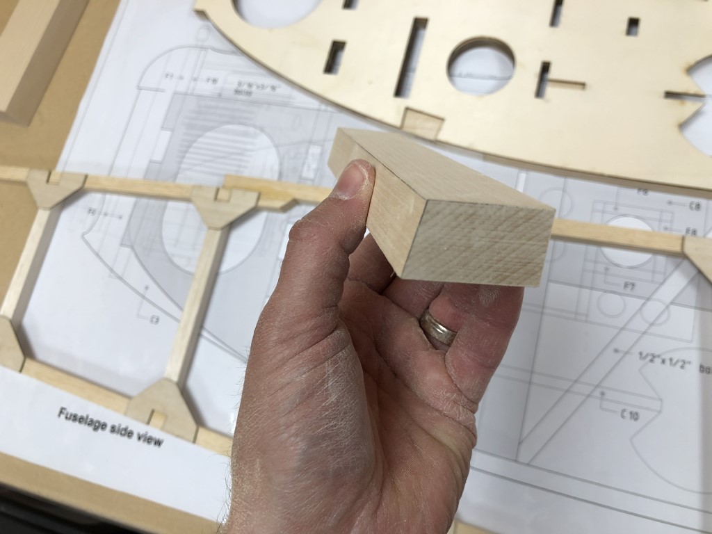
After finish sanding the cut blocks to the exact dimensions they came out very nice:

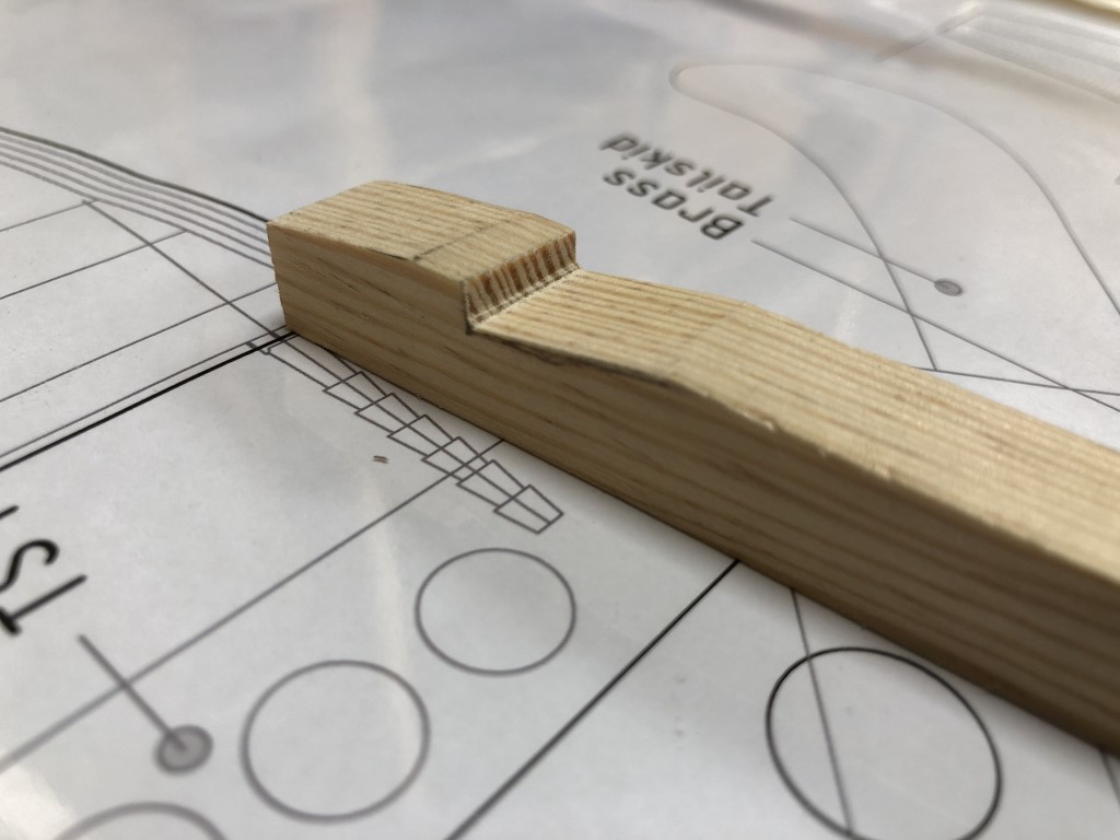
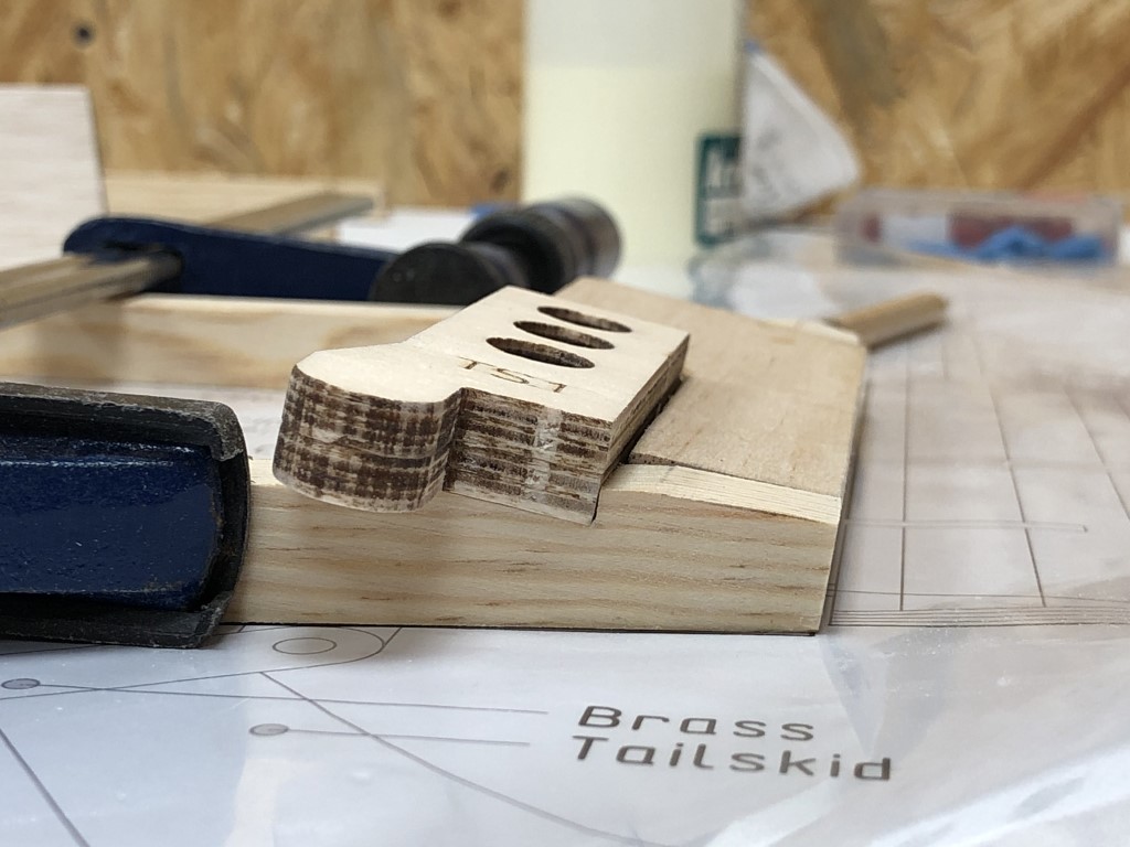
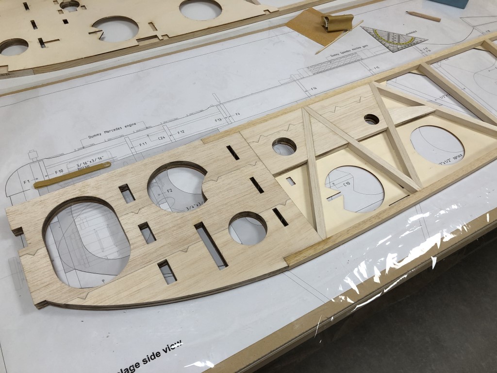
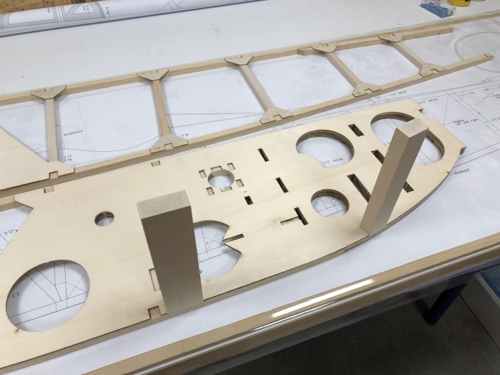
And the fit is just per-fect! Fits like a glove:

One more for the back and they’re ready, apart from the routed slots for the spring steel landing gear struts. I don’t want to route those slots before I’m sure about the wire thickness of the spring steel, so I’ll leave them like this and move on to the landing gear and its wing first:

I’m making good progress, but can’t finish up the fuselage before the exhaust and landing gear are done. In the meantime I might start working on the tail surfaces to keep things going.

Custom muffler part 1

The next step is to design and build the custom muffler. I’m going with a simple design, I hope it will be effective and that it doesn’t create too much back pressure. From what I got from experienced builders I think this could work. At first I planned filling the chamber around the perforated tube with steel wool but I’m told that will clog with oil residues over time, so I’ll leave that out. Let’s see how this plan works out!

The muffler will be made entirely of stainless steel. Thin-walled perforated tubing is hard to come by, so I ordered a thin-walled tube with a diameter of 15 mm and a thickness of 0.5 mm. I drew a template in CAD and taped it around the tube to drill the perforations myself. Easier said than done. I did expect the tube to deform, so I put a 14 mm thick spruce rod in it, but it got stuck by the burrs from drilling into the steel… also, a 4 mm drill bit turned out to be too thick and a 2.5 mm bit didn’t bite / slipped away. My solution was to mark all 230 holes lightly with the 4 mm drill bit and then puncture the steel with my 2.5 mm bit afterwards. Then, I removed the wooden core by drilling it out from the sides with a 12 mm wood drill, before cleaning up the inside of the tube with a file.

So, after drilling 460 holes with my column drill, some filing and sanding, I can say I’m rather proud of the result:

Next challenge: the exhaust pipe itself (outer wall). Buying a 40 mm stainless steel tube is easy, but they’re all 1.5 or 2 mm thick. We’ve tried to roll a 0.5 mm stainless steel sheet into a tube, which was doable, but TIG welding it turned out to be almost impossible (even with backing gas). Although a second attempt came out better, I’ve continued my search online for some ready made tubing. Hours into it, still no luck. Until I got the idea to search for a suitable thermos. And to my surprise I found a very small one that was just long enough. With an outer diameter of 45 mm it could very well be the case that the inner tube was about 40 mm wide. So I’ve ordered one and cut it open. Luck was on my side: the inner tube has a diameter of exactly 40 mm and the wall thickness is a beautiful 0.32 mm!!

After that, I cut two disk out of 0.5 mm stainless steel sheeting, bringing it to the exact right dimensions with a lot of sanding and patience:

Then I cut 15 mm holes in the center (drilled undersized and carefully brought to 15 mm with a milling bit and some sanding). It’s coming together nicely up until now:

My fellow club member helped me out with hard-soldering the parts together, as I do not have the equipment or the skills to do so myself. Very grateful to have such supportive and attentive guys in our hobby!

Lastly, I cut the open end of the scale exhaust at the right angle, and although I still have some sanding and shaping to do, it is already looking great:

And this is what it looks like from underneath. The inner assembly still has to be soldered to the outside wall, but at least the fit is perfect already:

Here you can see the end of the pipe from an angle, shows nicely that the functional exhaust pipe is hidden in the outer tube. From the side, you wouldn’t tell it’s there and it sure has the appearance of the original scale exhaust:

And this is what it’ll look like when it is fully finished and installed:

I also bought an extra cylinder exhaust tube from Roto, as it originally came with two different ones, sitting in different angles due to the different orientation of both cylinders. For me though, I want to bring them together in the center of the engine, so this seems easier to work with for my setup.

Now the challenge will be to create the transition from the original exhaust pipes to my custom muffler. Part of the challenge also is that the exhaust pipes attach to the cylinder heads using threads instead of being bolted on, which makes the geometry change while attaching it (the exhaust pipes point in the opposite direction) so I need to incorporate some flex tubing into my design. I hope it’s going to work out, because it would be totally awesome to have a working scale exhaust!

Here’s a small clip of the result up until now:

Firewall design finished

After trial fitting the engine in different positions, I landed on the following position, down and side thrust for the engine:

As mentioned before, I didn’t quite like the commercially available mufflers and didn’t know where to fit them inside the fuselage. Then, I got some valuable help from a fellow club member. We took up the challenge together and decided to try our luck at building a custom muffler in the shape and position of the original scale exhaust! Of course, it’s still not a sure thing we will succeed, but if we’d do that would be fantastic! This would be much more practical to install, it would be outside of the fuselage which is better for cooling, and above all, it would look awesome!

I took the only two photos that exist showing the original exhaust and measured the dimensions and angles, as well as the position where it would protrude the fuselage side. Then I’ve calculated the required volume. As far as I can see right now, position, angle and length would all be exactly scale, only the diameter would be slightly over-sized. Scale diameter would be 28 mm, I’m aiming at 40 mm right now.

Time to continue working on the firewall. This is the second version with better dimensions for the engine mount. I also drew the firewall from the kit on it for reference and cut a hole for the exhaust:

Here you can see the one degree side thrust and one degree down thrust:

The engine nicely fits onto the new firewall, fixed with 5 mm Allen bolts into T-nuts attached from the back:

Then I’ve built a test stand for running in the engine later on:

But it also serves another purpose: building the muffler! I’ve cut holes in such a way that if I fix the custom muffler into it, I have exactly the right angles both backwards and sideways. Also, I’ve added a piece that resembles the fuse side so I can test and fine-tune how the exhaust should pass through the fuse side:

But for running in the engine it wouldn’t be practical, and I also want to be able to work on the engine easily, so I’ve made it detachable using magnets:

The idea is to first build the custom exhaust, and when that’s finished and firmly attached, I will cut away the sides so the muffler can move freely when I’m running in the engine.

Building a test firewall

Working on the test firewall at the moment. I am building a test stand that doubles as a firewall construction test bed as well. The new firewall will be made of 9 mm birch ply and attached to the original firewall with bolts and washers, to get the right down and right thrust angles:

This new firewall will be glued to the sides as well.

After mounting the engine, I’ve tested the alignment of the prop shaft and checked the clearance of all engine parts with the fuse sides. I think this position works very well (which is one degree down, one right, and 10 degrees tilted to create more space for the exhausts):

Also, the carb fits well within the available space and doesn’t touch the fuse side:

I couldn’t resist checking what it looks like wit the prop on…:

Now, I’m going to redo the new firewall, to fix some small alignment issues, and reshape the cutout of the original firewall to accommodate the rear exhaust pipe. It takes a while but we’re getting there!

Reaming the wing tube holes

Tonight I spent some time adjusting the wing tube holes, to get them to the right size while aligning them on both fuselage sides. In this picture already halfway, enlarging the front hole from 41 to 42 mm:

And the other smaller hole will go from 25 to 27 mm.. not much of a change, but precise work, since this determines the alignment of the wing tubes. If the sides don’t match up exactly, the wings will not sit straight and that would look horrific. First, I’ve marked the new whole size and position:

And then I just sanded them to the right size, went well:

Checking if angles are perpendicular:

And checking the distance between the holes with the root rib:

After transferring the holes to the other side of the fuselage, I did another mock-up, this time including the wing tubes. Impressive sight, and surprisingly sturdy without any glue yet:

Alignment looks great. Did not spent any time on checking and final alignment, but by the looks of this, I think perfect alignment will be achievable quite easily. From the front:

And from the back, everything is looking sharp:

This is one of my favorite pics up until now, I’m really satisfied with how everything fits and the airplane really starts to come alive:

Small design steps

It’s been a little while since my last post, but I’m currently busy figuring out the engine installation and the exhaust configuration.

Meanwhile, I have measured my bending template for the lower longeron:

So I could transfer the exact curve to CAD, so we can add this template to the plans of the Fokker V.23!

And now, onto the firewall! I need a bit more space between firewall and prop, and I want 2 degrees of right thrust and 1 degree down thrust. I have two options to achieve that: use the stand-offs for the motor, mounting the new firewall straight onto the original one, or use the stand-offs for the new firewall so the motor sits flat on the firewall, which actually has my preference:

Muffler challenge

For a while now I’m thinking about where to position the muffler for the engine, because despite the roomy interior of the Fokker, there’s not much space left with this 85cc engine in it. The original ROTO mufflers for this engine look like this (and obviously I’d need two of them):

http://www.rotomotor.cz/rotomotor/eshop/3-1-Exhausts/0/5/79-Muffler-ROTO-for-35FS-85FS-85FSI-170FS

In terms of diameter (32 mm) they’re not that big, but it still is 23 cm long, which is quite substantial. And a combined muffler would be easier to build in.

After a short search I bumped into this muffler from Valach, which is also designed for a 85cc engine (a boxer, but that doesn’t make any difference). Both being four stroke engines of the exact same capacity, I’d say it would do:

https://toni-clark-shop.com/Silencer-for-Valach-VM-85B2-FS

This one is 6 cm in diameter but only 14 cm long. Which makes it a little more compact.

I was hoping that it would fit next to the engine, because that is exactly where the scale exhaust should be! It goes out on the right side, pointing downwards. But lengthwise it doesn’t fit, and in a vertical position I still think it won’t work:

Because I also need room for the cylinder exhausts, and I need to be able to cool the engine and muffler sufficiently, and this way, the rear cylinder and muffler are not going to help a lot with that.

And I also need some space for baffling towards the second cylinder. I really need to do that on this side as well, because the carburetor is on the other side of the engine, consuming quite some space over there as well:

And then I noticed this unused space behind F3, just below the tank floor and in front of the servo tray:

If I would mount it onto F3 with brackets, I can use 30 cm long connectors from the cylinder exhausts to here. The inlet for the muffler would point straight towards the front of the airplane, and the exhaust would point backwards in an angle, exiting the fuselage between the landing gear struts:

The downside of this, is that the gasses won’t come out of the scale exhaust location this way, which really is a pity. But I believe cooling everything, both the engine and the muffler, would be way easier, resulting in a better performing setup that is easier to build in and to maintain. Without formers, the engine and muffler layout would be like this:

This way, I can even create a cooling opening solely for the muffler, taking air from the underside of the fuselage (because it is positioned lower than the engine).

As I said, the scale exhaust would be a dummy one in this case, and the fumes would exist the fuselage on the bottom. From a distance, you won’t notice, and you’d have the advantage of the exhaust fumes not going over the wings, but from a scale perspective it is not such a great concession. But even if I would get a custom exhaust to fit the scale location, I would have trouble cooling and baffling everything efficiently.

So for now I think this will be my solution..

Fixing the wing tube box

As mentioned, one of the multiplex sheets was too thick (9 instead of 8 mm due to imperial to metric conversion). Therefore, the parts from that sheet didn’t fit in their cut-outs.. and since I didn’t want to sand them down completely, I took out the route jig for my Dremel:

Came out neat didn’t it?

And now, it fits like a glove, including the recess for the balsa cross-beam right next to it:

And next to the tabs, I wanted to alter something else too. My wing tube sleeves are 42,5 mm in diameter and my wing tube 40 mm. The box for the wing tube in the kit is also 40 mm, which would be perfect to accept my wing tube, but I rather have the sleeve to go through the fuselage as well. So I made a little CAD drawing to see how big the slots needed to be to accept the sleeve. Added benefit, I can use those pockets to fill them with epoxy making the connection even stronger:

First, mark the slots with a pencil:

And then route them free-hand:

And on the backside of those parts, the tabs needed thinning as well:

And in the end, the wing tube box slides together perfectly well:

This is how it looks from the inside:

And the wing tube sleeve fits in very nicely:

By the way, don’t know if I already mentioned it, but the wing tubes are Strongal tubes from Petraush in Germany, awesome stuff!

Fuselage preparations

Now the fuse sides are ready, I’ve started preparing building up the fuse. There’s still a ton of things to do before I can start gluing in the formers:

  • cut the longerons to the right length and angle, and recess them for TS1
  • finish shaping the tail block and glue it up
  • enlarge the holes for the wing tubes in the fuse sides, as they are drawn for the tube itself only, but I need them to be larger to accept its sleeve – meanwhile, I will use this step to perfectly align the wing tube holes with the two fuse sides so they match up
  • alter the firewall to accept the new engine, which is a tad longer, and if possible embed the down and right thrust into the firewall
  • route slots in the wing tube former box to accept the wing tube sleeves as well
  • adjust the thickness of the tabs of the wing tube former box to fit in the laser cut cut-outs
  • build a fuselage box for alignment while gluing

However, I needed to know how good the fit was, so here’s the first dry fit of the formers. I think it looks awesome!

But first, let’s start with finishing the tail block. I’ve added a small layer of balsa on top of the hand cut side, to give it a smoother appearance and to add some material for final sanding after assembly:

I was procrastinating this step because it is a bit complex, but today I decided to just go for it. The lower longeron has a double angle on the back (because of the curve) and a skewed recess that is not perpendicular to the longeron:

Why? Well, because the tail block has a cut-out for TS1 – the part that will hold the tail skid. And this part protrudes through the longer, while the tail block is lying in an angle to compensate for the bend:

And then, the other one.. not completely satisfied with the lower one on this photo, and I still need to cut one longeron to the right length (on the far left of this picture), but we’re almost there! In the background you can see the inspiring 3D render from the building plans :-)

Finishing up the fuse sides

After gluing on the ply doubler, I flipped the frame again from some last finishing touches. I must say I can really enjoy all these perfect joints:

The front half of the second fuse side, which came out even better than the first one I think:

And back together for some final sanding, sanding out the last little imperfections:

And behold, two perfectly matching fuse sides! I spent a lot of time aligning the holes for the wing tubes and all of the pre-cut slots for the formers, which will hopefully save me a lot of fiddling later on…:

Stacked them one more time to check alignment, front:

.. and aft of the fuselage:

I couldn’t resist dreaming a bit, it does almost fly doesn’t it…? :-)